Turning PC On with a Knock Using ATtiny45 and a Piezoelectric Sensor
Today’s post is something I’ve prepared for a long time. Hardware-wise it’s a simple thing – ATtiny45 emulating a PS/2 device, sending a keypress when three knocks are detected in the attached piezoelectric sensor (or piezo buzzer as they are also called). But if your computer can boot on PS/2 keyboard input and you have your computer stowed somewhere hard to reach (or just want to impress your friends), it’s a pretty neat little gadget! Here’s a video of it in action:
My PC takes a few seconds to put anything on display, but if you look at the bottom right corner, you can see the blue power LEDs light up immediately after the knocks.
What You’ll Need
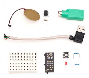
Hardware-wise this hack is super simple. You’ll need less than $10 in parts and many probably already have these lying around:
- ATtiny45. Actually, any ATtiny or ATmega with 4kB or more flash, A/D converter and two timers will work with small adjustments, and with -Os -DMINIMAL compiler flags also 2kB MCUs (ATtiny2313 doesn’t have a A/D but you can either work around it or use a button)
- Piezo buzzer and 1 Mohm resistor to act as knock sensor
- PS/2 connector, or alternatively a passive USB-PS/2 adapter (I have half a dozen from old keyboards and mice) and USB cable (like the one I used in my V-USB tutorial)
- Breadboard and wire. Alternatively you can solder it on a simple PCB like I eventually did.
- Optionally, a 4k7 ohm pullup resistor for RESET line, and a LED and 330 ohm resistor to indicate state
The Schematic and Breadboard Setup
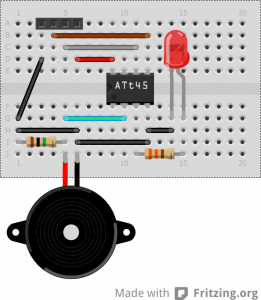
The PS/2 part as discussed in my minimal PS/2 keyboard post doesn’t require any other hardware than the ATtiny. The piezo element uses a 1 Mohm resistor like in the Arduino Knock Sensor tutorial, providing a path for voltage level to get back to zero over time. The LED is connected to PB4.
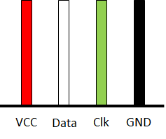
The PS/2 connector also provides power to the device. Instead of soldering a custom PS/2 connector for the project, I took a passive USB-PS/2 adapter I had lying around and used a multimeter to find out which USB pins correspond to the PS/2 ones. Not surprisingly, PS/2 GND and VCC are connected to USB GND and VCC. In my adapters, PS/2 clock was connected to D+ and data to D-. You can see the mnemonic printout I made on that one below, as well as one possible breadboard configuration.
Note that the USB connector mnemonic and the 4-pin header in the breadboard illustration have opposite orientations (as you can see from the black and red wires in each) – you can mentally rotate the USB wires 180 degress if you are “plugging it in” to the breadboard in your mind. :)
ATtiny45 Fuse Settings and Testing
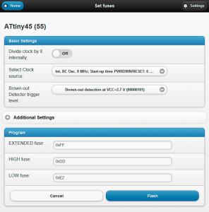
In order to have enough clock cycles for PS/2 communication, it’s recommended to disable the 8X clock divider in ATtiny45 default fuse settings, increasing the clock frequency from 1 MHz to 8 MHz. The clock doesn’t need to be very accurate, as PS/2 spec allows over 10 % variation from the 12.5 kHz we’re trying to achieve. The high/low fuse combination I went for is 0xDD/0xE2.
You can use avrdude to do it, but I like the AVRweb tool I developed some time ago, as I don’t have to reverse engineer my current fuse settings every time. It’s still in alpha stage so no guarantees, but it is very simple and has worked without problems for me so far. You may also want to check out this tip to make future flashing of ATtiny25/45/85 MCUs a breeze.
After changing fuse settings, I like to check that the clock frequency is what I think it is before doing anything else. Here’s something that should blink the LED on PB3 every second or so:
#include <avr/io.h>
#define F_CPU 8000000UL
#include <util/delay.h>

#define PIN PB4

int main(void) {
    DDRB = _BV(PIN);

    while(1) {
        PINB |= _BV(PIN);
        _delay_ms(500);
    }

    return 1;
}
Once the clock frequency is OK, it’s also a good thing to see if vibrations in the piezo sensor can be detected correctly. This required correct A/D converter settings for the ADC register to work like we want it to. Here’s another test program for that:
#include <avr/io.h>
#define F_CPU 8000000UL
#include <util/delay.h>

void adcStart() {
    // ADMUX REFS0:2 set to 0 means Vcc as voltage reference
    // ADMUX ADLAR also to zero so ADC value is right-adjusted (LSB)
    // ADMUX MUX[3:0] to 0011 to select PB3
    ADMUX = _BV(MUX1) + _BV(MUX0);

    // ADCSRB (ADC Control and Status Register B)
    ADCSRB = 0; // Free-running, not bipolar or reversed input polarity

    // ADCSRA (ADC Control and Status Register A)
    // ADPS[2:0] 110 to select prescale of 64 resulting in 125kHz @ 8MHz
    ADCSRA = _BV(ADPS2) + _BV(ADPS1);
    ADCSRA |= _BV(ADATE); // AD auto trigger enable (based on ADPS bits)
    ADCSRA |= _BV(ADEN); // ADC enable
    ADCSRA |= _BV(ADSC); // ADC start conversion
}

#define PIN PB4

int main(void) {
    uint8_t leds = 0, knocks = 0, state = 0;

    DDRB = _BV(PIN);
    adcStart();

    while(1) {
        if(ADC > 10) {
            PORTB |= _BV(PIN); // LED on
            _delay_ms(500);
            PORTB &= ~_BV(PIN); // LED off
        }
    }

    return 1;
}
When you run it, the LED should flash for half a second every time you tap the piezo element. You can download both of these test programs with a simple Makefile that lets you say make blink.hex to compile the blink test, or make piezo.flash to both compile and flash it (you’ll need to edit the Makefile if you’re using a different ISP programmer than USBtiny).
The Program Code
The actual program code that you can download or clone from Github is a complete PS/2 device that will respond intelligently to most PS/2 protocol commands from PC, although it will also ignore most of it, like setting typematic rate or other behavioral things. However, it is plenty enough so you shouldn’t get any errors about malfunctioning keyboard device like I did with my earlier project.
I won’t discuss the code in detail here – you can read my previous post on state machines with C callbacks after which you should be able to understand the basic mechanism how the PS/2 communication is handled. I have separated the code in several files – most of it is rather straightforward setting up of A/D conversion, timers, etc. which you can read better tutorials in the net or AVR Freaks Tutorials forum than I have space to cover here. Here’s a quick rundown of the source files:
main.ccontains the main method and program logicps2config.hhas pin definitions and some general configuration stuffps2.candps2.hcontain the PS/2 communications codetimer.candtimer.hinclude timer setup for ATtin25/45/85 as well as ATtiny2313. Other tiny/mega chips are left for the reader as exercise ;)adc.candadc.hcontains A/D converter setup and reading codering.candring.hcontains a simple ring buffer implementation for communication between PS/2 code and main program logic. It is not re-entrant or anything, but current use should not cause problems (although I have no mathematical proof about it)
The code is released under GNU GPL v3. It is by no means a complete toolkit for every PS/2 project out there, but should provide a great starting point for such an endeavor. Implementing fully bomb-proof PS/2 device side code that can handle all possible interruptions by PC (some of which are extremely unlikely but still within spec) is something that would require several days of additional coding and even some information that I could not easily find from the net. I’m fairly certain that the current implementation fares as well as most “PS/2 compatible” USB keyboards, but I know that I could jam it with carefully constructed host side code…
The heart of this hack, however, lies elsewhere than in the PS/2 implementation (which is the “hard part”). The knocking logic is implemented as follows:
if((adc = adcRead()) > ADC_TRESHOLD && millis > 500) {
    if(millis > 3000)
        knocks = 1;
    else
        knocks++;

    if(knocks >= 3 && ringEmpty(receiveBuffer) &&
       ringEmpty(sendBuffer)) {
        sendCode(0x29);
        state = 1; // indicate we're sending
        knocks = 0;
    }

    millis = 0;
}
I initially just had one knock, but it became a nuisance when the device would type space whenever I placed something on the table. Now every knock increments a counter, and next knock won’t register until 0.5s after the previous one (because one knock will cause vibration for tens of milliseconds). Furthermore, if more than 3 seconds have elapsed since last registered knock, the counter will start from beginning, so you don’t accumulate three knocks in, say, eight hours.
Flashing the Final Software and Testing that It Works
You can either download the github version or use git clone git://github.com/jokkebk/ps2kb to get it. If you’re using the exact things I am (ATtiny45 and USBtiny ISP programmer) you can just run make run to compile the .hex and flash it. There are some settings in the Makefile you might want to take look at if you desire to build a minimal version for 2 kB MCUs or want to omit the LED (just remove -DLED=PB4), use a button instead of a piezo or something like that.
A handy tool to check if everything works is the Arduino-based PS/2 tester I featured some weeks ago. You can try sending “EE” (echo) command to see if the device responds with “EE”, and other PS/2 commands. Furthermore, you can tap the piezo element three times (remember to wait 0.5 seconds between each tap, or you’ll need extra taps) and see if the device sends 0x29 (spacebar pressed) and 0xF0, 0x29 (spacebar released) like it should.
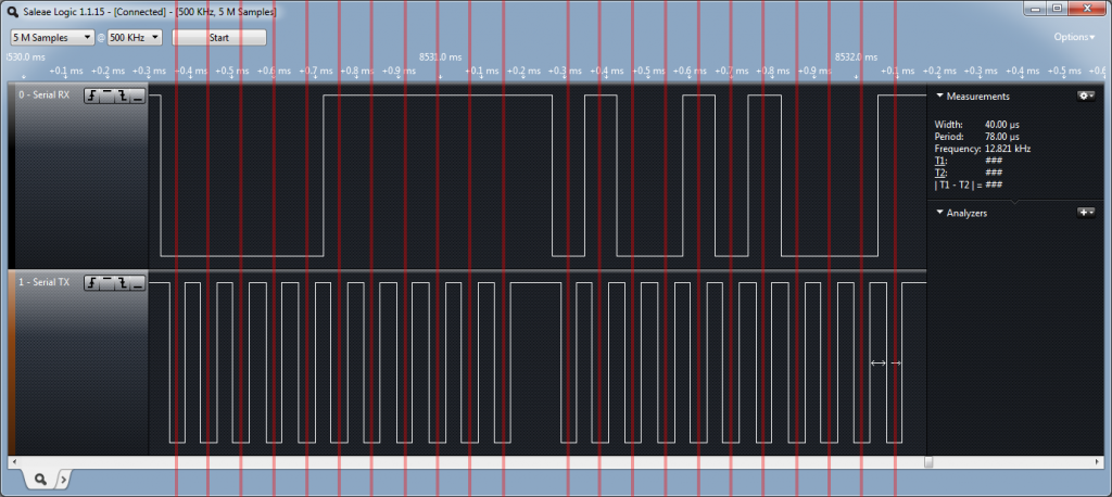
I recently got a Saleae Logic analyzer which was a big improvement over my earlier, sometimes creative, DIY attempts that all left a bit to desire. The screenshot above shows two bytes of PS/2 communications from device to PC. I’ve added red lines on clock low for reasons we’ll see shortly. Even without PS/2 analyzer plugins (I’m planning to try my hands at writing one at some point) the PS/2 traffic is quite simple to decipher:
- When the device is sending, you’ll see the data line going down first, then clock
- PC reads bits when clock is low, device changes them when clock is high
- High data line means one and low zero
- Each byte is preceded by start bit (zero), and followed by parity (odd parity) and stop bit (one)
- Byte is sent the least significant bit first, e.g. 10101111 would generate 1,1,1,1,0,1,0,1
From the screenshot, we can see that the first sequence of eleven bits is 0,0,0,0,0,1,1,1,1,1,1 which means start bit, a byte 11110000, i.e. 0xF0 (here most significant bit is first), parity bit of 1 and the stop bit. The second set of bits is 0,1,0,0,1,0,1,0,0,0,1 from which the data portion is 1,0,0,1,0,1,0,0, i.e. the data byte is 0x29 (00101001, note again the reversed order in written notation). So what we are seeing here is the break code for spacebar – 0xF0, 0x29. Works nicely!
When PC is sending it begins the exact opposite way by first pulling clock low, then pulling data low and releasing clock so the device is free generate the clock signal. Data line is manipulated on clock low, and the device reads the data on clock high. There is also a special way to acknowledge the sent data, see for example this PS/2 protocol page for details.
Installation
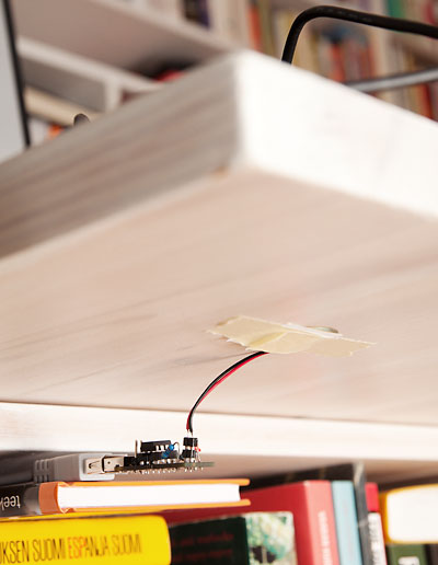
Once everything is working, just attach the device to the bottom of your desk (I used a piece of paper and tape to make a “pocket” for the sensor, and off you are to amaze your friends! And of course, if you have a hard-to-reach power button, you will actually save several seconds of your valuable time on every boot. I counted that with about 40 hours of work put into this project and its spinoffs, I’ll be on the plus side in half a century or so!
Final Remarks
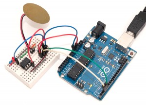
As you can see from the final image, I’m actually using a more compact version of this project. I actually designed a PCB and ordered three of them from OSH Park for $3.90. I’ll be covering the design process and end result in another post hopefully pretty soon, so be sure to check back in a couple of weeks! Or even better, subscribe to the RSS feed, I also have a Saleae logic analyzer test and a few other things planned in the near future. :)


