Power up your computer wirelessly with Wemos D1 mini
Tired of reaching for that power button? Or perhaps you’d like to be able to turn on your PC when travelling? I sometimes like to do that to access some local files (or software via VNC), but dislike leaving the PC on for days “just in case”. This article explains how you can do it with the $3.50 Wemos D1 mini.
Wake-on-LAN is of course a great idea, but it only works if your PC is physically wired to the router. Wake-on-WLAN theoretically should work for WLAN as well, but here’s a shocking revelation: it usually does not, as it requires your PC to power up your WLAN card for it to receive the magic WLAN packet, and router support. At least I’ve never had a combination of network card and router that would work.
I used to have a nice DIY knock-sensor to PS/2 thingy, but the piezo kept dropping out, and got tired of repeating the required sequence of knocks. So I thought it would be cooler to have just a Bluetooth button I could use to do the same. I had a WLAN enabled Wemos D1 mini board lying around, and it only draws less than 100 mA of power, so I thought to find out if I could make it listen to a “magic packet” and boot up my PC. Turns out it was easier than I even thought!
Note that this project involves opening your PC case and playing around with your motherboard power switch wiring. Everything should be relatively hard to screw up, but if done wrong, you may get electrocuted, you may stick a screwdriver where it shouldn’t go and damage your motherboard or other components, so proceed with your own risk!
ATX power switch fundamentals
My initial idea was to code a PS/2 emulation into the D1 (my MB has “power on PS/2 keyboard” option). However, it is not a trivial protocol to implement (which I know, having done that earlier for the knock sensor hack linked above). Then it occurred to me: PCs have ATX power switches, which are just simple momentary switches connected to motherboard with a pair of jumper wires. How hard it would be to emulate the power switch? Turns out dead simple.
ATX power connector has two pins on the motherboard. One pin is GND and the other pin has weak pullup to VCC on the motherboard. When you press the ATX power switch, those pins get shorted, and the pin with pullup is drawn to GND. The motherboard senses this and turns your power on. Or off, if you do it while your computer is turned on. Just use a multimeter to check which pin is which. I measured 3.3V on the “sensor” pin. You can look up this example or your motherboard manual for the pin header layout, or just follow the “POWER SW” wire from your ATX case. If you want to “practice” before wiring the Wemos in, remove the POWER SW jumper cable from the motherboard, and use a flat screwdriver to short the power switch pins. Your PC should power up like you had pressed the power switch.
My motherboard (and I assume this is true for most MBs) gives USB power even when turned off, and because it shares the ground with the MB itself, triggering the power switch is super easy: Just wire the “power sensor” pin (the one from ATX power pair that measures 3V+ when idle) to a microcontroller. Normally you’ll have the MCU pin as “input” without pullup, so the 3V stays undisturbed, but when you want to pull it low, momentarily switch the MCU pin to output, set level to LOW, wait a second (or maybe 0.1s), and then switch it back to input. Easy! Below’s the Arduino version of this procedure, just for reference.
pinMode(D1, OUTPUT);
digitalWrite(D1, LOW);
delay(100);
pinMode(D1, INPUT);
Wemos D1 mini code
Before attempting to upload the script below, I recommend you to visit https://www.wemos.cc/, navigate yourself to D1 mini page and read the Arduino tutorial and see if you can upload some simple blinking LED demo to the board. If you cannot, it’s time to start googling around what the hell is wrong, welcome to the world of do-it-yourself electronics. :)
Once you are comfortable with flashing the D1 with custom software, I recommend you to try out some of the ESP8266 Arduino examples to see if you can connect to your home router successfully. There are a ton of tutorials out there, so take the time to get to know how the ESP8266 Arduino libraries work.
Only after you 1) can reprogram the D1 successfully with Arduino, and 2) verify that your D1 can connect to the router should you proceed with flashing the following sketch:
#include <ESP8266WiFi.h>
#include <WiFiUdp.h>

const char* ssid     = "YOUR-ROUTER-SSID";
const char* password = "passW0RD";

WiFiUDP Udp;
const int localUdpPort = 1234;
char incomingPacket[255];  // buffer for incoming packets

void setup() {
  Serial.begin(115200);
  delay(100);

  connectWifi();
}

void connectWifi() {
  Serial.println(ssid);
  WiFi.begin(ssid, password);

  while (WiFi.status() != WL_CONNECTED)
    delay(500), Serial.print(".");

  Serial.println("Connected! IP address: ");
  Serial.println(WiFi.localIP());

  // not sure if this can be called multiple times...
  Udp.begin(localUdpPort);
}

void loop() {
  if(WiFi.status() != WL_CONNECTED) connectWifi();

  if(Udp.parsePacket()) {
    int len = Udp.read(incomingPacket, 255);
    incomingPacket[len] = 0;
    if(len==1 && incomingPacket[0] == 'X') {
        pinMode(D1, OUTPUT);
        digitalWrite(D1, LOW);
        delay(100);
        pinMode(D1, INPUT);
    }
  }
}
The code is a toned down version of the basic UDP server example, with a twist: Once an incoming packet arrives, the system checks if the content is “X” (you may want to change this to something else), and if it is, it switches the D1 pin to output, and pulls the line low for 100 ms (0.1 seconds), then switches D1 back to input (the default).
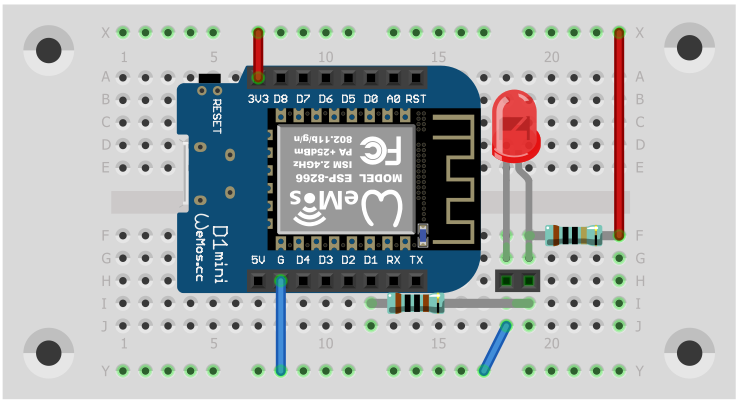
Wemos D1 mini wiring
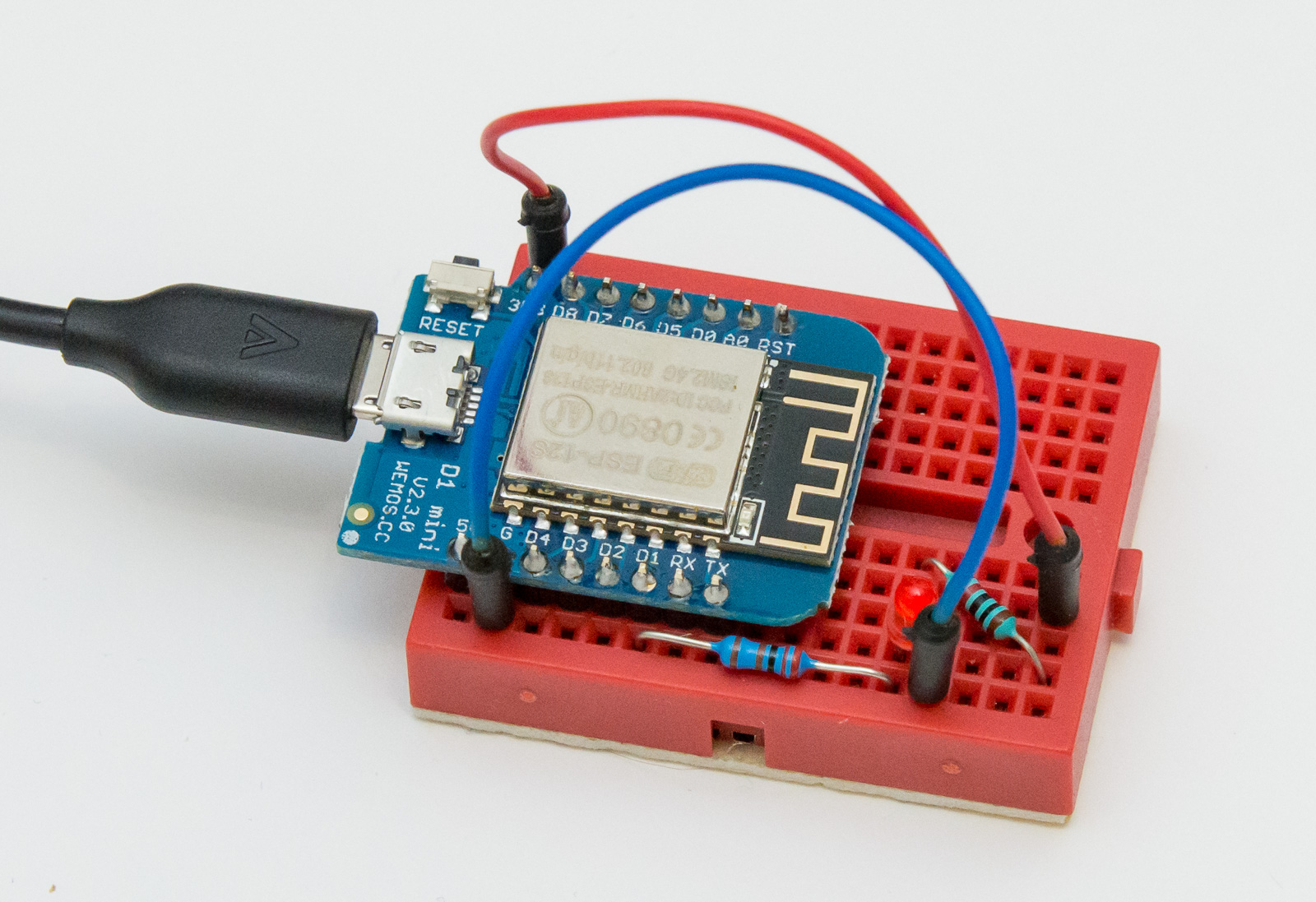
To see if you have it working, it’s a good idea to wire a LED test circuit in place of ATX power switch jumper cables. ATX pins have GND and weak pullup to VCC, so in the above image (and breadboard diagram below), the Wemos D1 “G” is connected to LED-, and “3V3” to LED+ with a 10k resistor in between. This should give out a weak light. Wemos D1 pin “D1” is connected to LED+ via a 2k resistor, so when it’s in input mode, the LED stays on, but when D1 is set as output and pulled to GND, the D1 pin overpowers the weaker VCC pullup (2k vs. 10k), and LED turns off.
Triggering the Wemos
Once you have the sketch uploaded and your test breadboard set up, look up the IP address of your Wemos board (you can use Arduino’s serial monitor, or just go to your router admin panel and see connected devices, there should be an ESPxxxxx device visible). The following Unix command sends the magic UDP packet to Wemos, assuming your Wemos’ IP address is 192.168.1.102:
echo -n X > /dev/udp/192.168.1.102/1234
If everything works, running the command should result the LED blinking dark for 0.1s. On Windows, you can google around for alternatives, there are UDP packet tools and all kinds of options available.
Wemos D1 mini ATX power switch in action
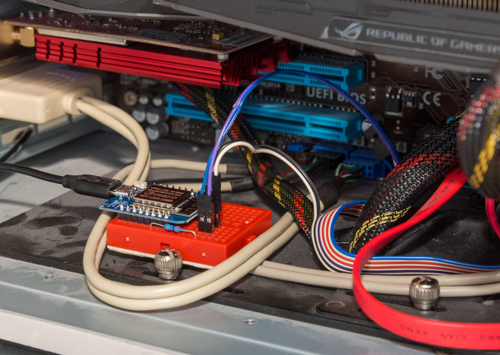
Super. Now you just pull out the LED, and connect the D1 via a resistor to the ATX power switch pin that has the 3V pullup. If you like your power switch to work as well, you can wire the POWER SW jumper cable to breadboard, and from the to the motherboard, and just connect D1 to the same pin. Below you can see my version in action — I chose to keep the breadboard also because it provides electrical isolation from the metal case. USB needs also to be connected, otherwise the Wemos will not get any power, rendering your solution pretty useless. :)
Further thoughts
That’s it! You can now use a magic UDP packet to the Wemos to boot up (and down) your computer. If you are feeling really adventurous, you can configure your router to do NAT forwarding for UDP port 1234 from internet, but it also means anyone at all can accidentally (or on purpose) mess with your computer power. I myself am exposing the UDP only in local wireless network, and using a Raspberry Pi in the local network (which I can connect to with SSH) to power up my computer.
I have also set up the Pi automatically to send the packet when my $8 Chinese Bluetooth media button is connected, so I can trigger the power up from a few metres away (the button is conveniently taped to bottom of my desk, which is a lot easier to reach than the Antec P180 power switch that sits behind the front door of the case.
If you want additional safety, you should probably change the “X” in the firmware and UDP packet to something unique. But that’s left as an exercise to the reader. Enjoy!
Further note: The Wemos D1 seems to occasionally stop working (like after 1 month of uptime), so you may need to plug the USB cord out and put it back in every once in a while. I do this before any trip, so I can be rather sure it works the following week or two. A more robust option would be to have some kind of watchdog or periodical reboot every day or so.