Minimal PS/2 Keyboard on ATtiny2313
I recently got myself a mechanical keyboard (to be precise, a Happy Hacking Keyboard Professional 2). One side effect of this switch was, that the new keyboard no longer works with simple passive PS/2 adapter. And the only type of input my current motherboard can be configured to power up on is spacebar from a PS/2 keyboard.
Well, I had read from somewhere that PS/2 protocol is not too complex, so I decided to find out if I could make a simple gadget that would send spacebar keypress over PS/2 when a switch was toggled. That turned out to be quite easy (with some limitations, read the end of this post to find out more).
PS/2 basics
The Wikipedia page for PS/2 connector already looked promising – there are GND and VCC pins straight available, and only two additional (open collector type) lines are needed for data and clock lines. Communication is bi-directional with the keyboard providing clock signal and sending end toggles data line while the receiving end listens.
Open collector basically means that the lines have a pullup resistor to VCC, and either end (PC/keyboard in this case) can pull the data line low while the other end monitors the data line. Because only active action either end can take is to pull the line low, no contention between the two ends can happen so there’s no need to be certain that the other end isn’t trying to pull line up while you’re pulling it down (which may easily end up with some overloaded MCU pins).
Because in this project I was only interested in sending one keypress (and key release in order not to jam the spacebar down), I chose to ignore any communication from PC to the keyboard. Therefore only basic operation that I needed to implement was “send a byte over PS/2”. Turns out this is rather easy: Keyboard generates clock pulses and in the middle of “high” clock period, data line is toggled, as PC reads data when clock goes from high to low state. Before 8 bits, a start bit (0) is sent, and after the byte, there’s and end bit (1) and parity bit (0/1 depending if the byte contained even or odd odd or even number of ones).
More details on the PS/2 the protocol can be found from Adam Chapweske’s PS/2 article. I suggest you to read it out if you want to understand better what’s happening in the code.
The circuit
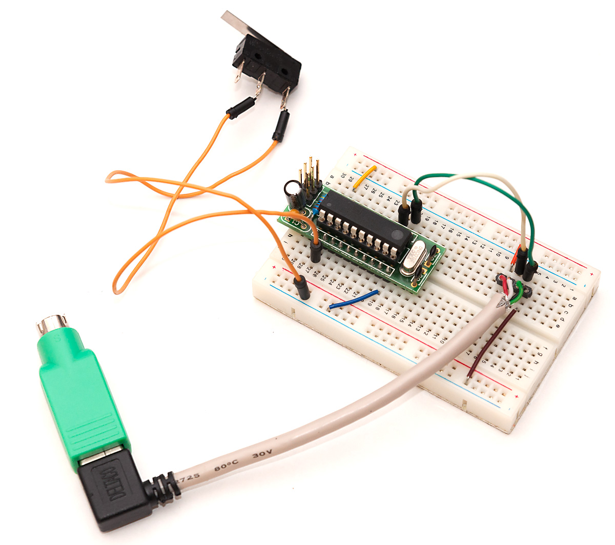
I was almost starting to solder a PS/2 connector to a pin header, when I realized that I’ve read that most USB->PS/2 adapters are passive kind – that means they just rewire the pins to USB connector. Armed with a multimeter, it quickly became obvious that I had several old adapters that wired VCC and GND to same pins in USB, and used D+ for clock and D- for data. Therefore I could re-use my USB to breadboard -adapter in this project, as you can see in the image above.
Other wirings are super simple – a switch to PD0 (connects to GND so I can use internal pullup to keep it at logic 1 when button is not pressed), and clock and data to PB0 and PB1, respectively. You can look at the bigger picture for example wiring. Note that I used my ATtiny2313 breadboard header which also has 20 MHz crystal in it, but the project will work great with internal clock also.
The code
Because ATtiny2313 pins can function both as inputs and outputs, and have internal pullup resistors, the PS/2 data and clock lines can be wired straight to pins without pullups or transistors. First part was to write a few helper routines to set clock and data lines high (make pin an input, toggle pullup resistor) and low (turn off pullup first, then set pin as output), and read the current pin states (only useful when lines are high so one can see if PC side is holding either low):
#define PS2_CLOCK_DDR DDRB
#define PS2_CLOCK_PORT PORTB
#define PS2_CLOCK_PIN 0
#define PS2_CLOCK_INPUT PINB

#define PS2_DATA_DDR DDRB
#define PS2_DATA_PORT PORTB
#define PS2_DATA_PIN 1
#define PS2_DATA_INPUT PINB

static void clockHigh(void) {
	PS2_CLOCK_DDR &= ~_BV(PS2_CLOCK_PIN); // set as input
	PS2_CLOCK_PORT |= _BV(PS2_CLOCK_PIN); // set pullup
}

static void clockLow(void) {
	PS2_CLOCK_PORT &= ~_BV(PS2_CLOCK_PIN); // zero output value
	PS2_CLOCK_DDR |= _BV(PS2_CLOCK_PIN); // set as output
}

static void dataHigh(void) {
	PS2_DATA_DDR &= ~_BV(PS2_DATA_PIN); // set as input
	PS2_DATA_PORT |= _BV(PS2_DATA_PIN); // set pullup
}

static void dataLow(void) {
	PS2_DATA_PORT &= ~_BV(PS2_DATA_PIN); // zero output value
	PS2_DATA_DDR |= _BV(PS2_DATA_PIN); // set as output
}

#define readClockPin() (PS2_CLOCK_INPUT & (1 << PS2_CLOCK_PIN))
#define readDataPin() (PS2_DATA_INPUT & (1 << PS2_DATA_PIN))
Once the basic routines are in place, it’s quite simple to initialize the pins or send a byte over PS/2:
#define CLK_FULL 40 // 40+40 us for 12.5 kHz clock
#define CLK_HALF 20

void ps2init() {
	clockHigh();
	dataHigh();
}

int ps2write(unsigned char data) {
  unsigned char i;
  unsigned char parity = 0;

  if(!readClockPin() || !readDataPin())
	  return -1; // clock or data low

  dataLow();
  _delay_us(CLK_HALF);

  // device sends on falling clock
  clockLow();	// start bit
  _delay_us(CLK_FULL);
  clockHigh();
  _delay_us(CLK_HALF);

  for(i=0; i<8; i++) {
	  if(data & 1) {
		  dataHigh();
		  parity++;
	  } else
		  dataLow();

	  _delay_us(CLK_HALF);
	  clockLow();
	  _delay_us(CLK_FULL);
	  clockHigh();
	  _delay_us(CLK_HALF);

	  data = data >> 1;
  }

  if(parity & 1)
	  dataLow();
  else
	  dataHigh();

  _delay_us(CLK_HALF);
  clockLow();
  _delay_us(CLK_FULL);
  clockHigh();
  _delay_us(CLK_HALF);

  // stop bit
  dataHigh();
  _delay_us(CLK_HALF);
  clockLow();
  _delay_us(CLK_FULL);
  clockHigh();
  _delay_us(CLK_HALF);

  _delay_us(50);

  return 0;
}
The send code is quite long, but it’s quite easy to understand once you realize that we are just generating a clock signal with clockLow()/clockHigh() and stopping in the middle of clock high to toggle data signal.
Now sending a spacebar over PS/2 consists of two actions: first we send the “make code” for the key pressed. For spacebar this consists of one byte, 0x29. Then we wait a bit for the keypress to register and send a “break code” which means the key has been released. For spacebar this is two bytes, 0xF0 0x29. The main method for our project becomes simply:
#define BUTTON_DDR DDRD
#define BUTTON_PORT PORTD
#define BUTTON_PIN 0
#define BUTTON_INPUT PIND

int main() {
	ps2init();

	BUTTON_PORT |= _BV(BUTTON_PIN); // pullup on button

	while(1) {
		if(!(BUTTON_INPUT & _BV(BUTTON_PIN))) {
			ps2write(0x29);
			_delay_ms(50);
			ps2write(0xF0);
			_delay_ms(10);
			ps2write(0x29);
			_delay_ms(200);
		}
	}

	return 1;
}
Feel free to make the delays shorter, it worked fine on my PC, but I now realize I should’ve probably used a lot shorter delays between make and break, and especially between the bytes of the break code. The last delay is just to prevent one click sending a dozen spacebar presses (it takes at least 0.1s to release a switch). Not that it makes much difference when computer is booting up, but still.
Final remarks
You can grab the full source code and a makefile from here: ps2space.zip. The project works great on my computer, but try this project at your own risk, mistakes in wiring (e.g. a short between VCC and GND) can damage your motherboard!
Because the device happily ignores any attempts the PC makes at communicating with it, you cannot probably use this project to send arbitary keypresses after boot – my motherboard decided I had no keyboard at all when I entered BIOS (means I need to unplug this project every time I want to go there, which is thankfully very seldom), and Windows complained of device failure. I’m planning to study the protocol a bit futher to overcome these limitations, so stay tuned. :)
Finalyl, big thanks to Arduino PS2dev authors Chris J. Kiick and Gene E. Scogin who had written similar code and released it to public domain. Their routines have served as inspiration for the PS/2 code presented here.