Shut down my Pi today and thought to make a copy of files in its SD card. This is what mount /dev/sdf2 /mnt had to say:
mount: wrong fs type, bad option, bad superblock on /dev/sdf2,
missing codepage or helper program, or other error
In some cases useful info is found in syslog - try
dmesg | tail or so
Great. After trying parted and fsck, it became apparent that for some reason, the root partition is marked as being 1 block longer than the physical card. Must be a bug with Raspbian partition expansion or something.
Thankfully, I found this gold nugget which suggested using resize2fs to fix it. Turns out I had to run e2fsck first (and say “y” a couple of times):
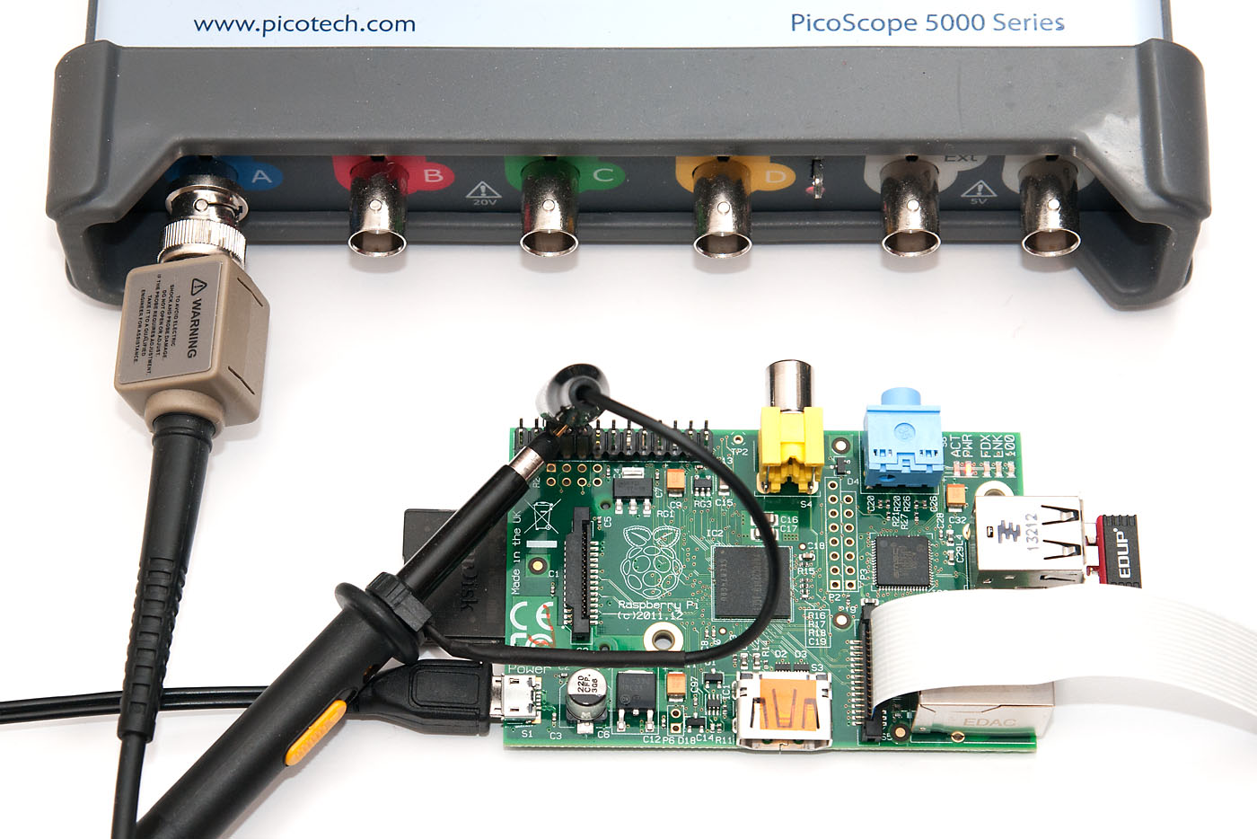
The new Raspberry Pi model 2 is out and the Pi world seems more popular than ever. My 2012 benchmark of different RaspPi GPIO access methods has been getting a lot of hits, so I thought to revisit it, and have now updated all the benchmarks with latest versions of firmware and GPIO libraries. I’ve also upgraded my oscilloscope to PicoScope 5444B, so the scope bandwith limitations I had earlier are now gone. :)
Because the benchmark has been linked from many other sites, I’ve just updated the old post to keep links pointing to right places.
Ever had that moment where you started coding X and instead spent four hours doing Y instead? I just had it, and it stemmed from a quite simple idea: let’s do an embedded SVG bar chart with React (nice library by the way)! Because I just started with Bootstrap which makes it really simple to scale your content to the device at hand, I also wanted the diagram to scale. Easy, right? WRONG!!!
<svg version="1.1" width="100%" viewBox="0 0 200 100">here are some primitives</svg>
The viewBox attribute defines the internal coordinates for the SVG, and the width attribute should ensure the SVG fills the container. And it does, at least on desktop. And mobile Chrome. But not Android default browser. I tried different settings of preserveAspectratio. I tried CSS tricks that should work but they wouldn’t. After some hours, I gave up and went to sleep. And this morning I found this nugget: WebKit long had a bug, where SVG element is resized to 100% height, which on mobile device was interpreted as screen height (not the parent element)!
So long story short, if I use my S5 in portrait mode, the 1080×1920 screen makes the above SVG element 1920 pixels high, with 1080×540 (2:1) diagram in the middle of huge white area. The bug is reported in 2012: https://bugs.webkit.org/show_bug.cgi?id=82489. This was supposedly already fixed, but seems the new version hasn’t trickled to my mobile OS yet. Thankfully, the fix is quite simple and does seem to work, just add max-height to the element:
<svg version="1.1" style="max-height: 100%" viewBox="0 0 200 100">here are some primitives</svg>
I didn’t even need the width=”100%” because that seems to be the default. Doesn’t hurt, though. So, just sharing this for everyone, maybe Google will index this and help others in need.
Another short web coding tidbit for today. I’ve been working on a Bottle.py+SQLAlchemy based backend for a personal project, and found very little information on how to convert a SQLAlchemy Core resultset into JSON.
Here is a glimpse into what was most commonly suggested. Tons of code. But wait, did you know you can cast a row into a dict? No? Well, it makes a world of difference:
import json# somewhere here, accounts table is defined with SQLAlchemy syntaxdef example(): res = conn.execute(select([accounts])) # return all rows as a JSON array of objects return json.dumps([dict(r) for r in res])
Now, which do you prefer, the last line or the longer 17-lines in StackOverflow? There is a slight problem though, namely date and numeric(x,y) fields, as they will turn into datetime.date and decimal.Decimal types. Thankfully, Python’s JSON library can be provided with a function to handle classes that the library itself doesn’t handle:
import decimal, datetimedef alchemyencoder(obj): """JSON encoder function for SQLAlchemy special classes.""" if isinstance(obj, datetime.date): return obj.isoformat() elif isinstance(obj, decimal.Decimal): return float(obj)def example(): res = conn.execute(select([accounts])) # use special handler for dates and decimals return json.dumps([dict(r) for r in res], default=alchemyencoder)
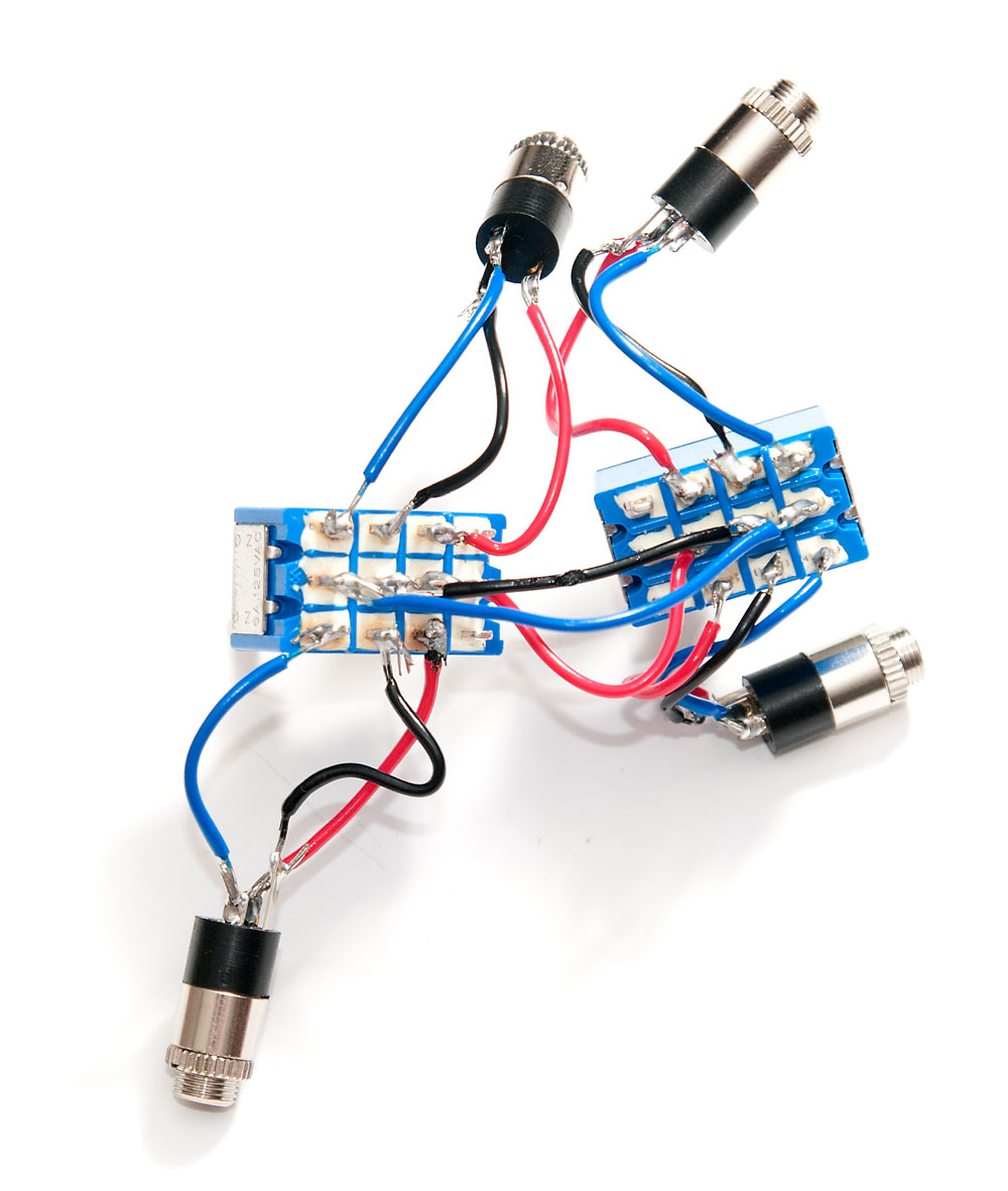
I’ve had a small problem over a year: I have two headphone amplifiers, a transistor-based O2 headphone amp, and a tube-based Little Dot MKII. I also have two sets of headsets. Because switching the cables all the time is somewhat tedious, I haven’t really used the other amp and headphone set.
There are several Y switches that you can buy, but most seemed either expensive or mostly tailored towards electric guitar enthusiasts. And I would still need to combine two Y switches to toggle between the two amps and headphones. As the construction is really simple, I decided to solder my own. Here’s a short tutorial on how to make one yourself. You’ll need:
4 audio connectors (I chose 3.5mm over RCA), two to each end
2 switches with at least 3 connectors (left, right, ground) – I chose two 4 way switches
A box where you can drill holes for the connectors and switches
Small length of wire, some solder and soldering iron
1. The Schematic
The design of the switch is extremely simple. In both ends, three wires come from each of the two connectors to a switch, and the switches are connected to each other. I chose not to combine any ground lines to avoid ground loops. You need also to select a switch which breaks the connection on one side before connecting the other so the amplifiers will not feed into each other.
2. Soldering the wires
Despite the simple construction, there is a lot of soldering involved. Each of the four connectors will have ground plus left and right channels, and all have the switch on the other end. That makes 24 solder points (4x3x2), and there’s six more between the switches for a total of 30 points. The 3.5mm connectors had small “L” and “R” markings to tell which channel is left and which is right. I used different colors of wires for each type to avoid mixing L, R and ground.
A web coding tip for a change: After a long coding hiatus, I decided to try my hand at recoding my web-based budget software with AngularJS on the client side and Bottle.py handling the backend. Superb and compact combination, by the way!
Bottle.py comes with a great minimalist templating engine called SimpleTemplate, which uses {{ var }} syntax for inline variables. This does not mix well with client side AngularJS which uses the exactly same delimiters. There is an easy way to change Angular’s syntax with $interpolateProvider, but guess what? Many AngularJS additions, like the datagrid component ui-grid (previously ng-grid) don’t respect this setting, and just plain break with custom delimiters. Not nice
So, what if you want to change SimpleTemplate syntax? Turns out there is very little documentation for it, even if it’s a single line change. Just locate this line in bottle.py:
default_syntax = '<% %> % {{ }}'
…and change it to:
default_syntax = '<% %> % [[ ]]'
And that’s it! Actually, not quite, because bottle default error page template is hardcoded for curly braces. So locate ERROR_PAGE_TEMPLATE in the same file, and change every {{var}} to [[var]].
There is elegant code in bottle.py that seems to enable replacing the default syntax, but unfortunately the only tip for using it seemed somewhat complicated. So I opted for this simple hack. I’ll sure regret it when I next time update my bottle.py, but, well, that’s not in this month, right?