Using The SSD1306 OLED on a Wemos S2 Pico ESP32-S2 board
Just received the Wemos S2 pico board from AliExpress, and thought I'd write a simple tutorial on how to use it with Arduino, as Wemos' Getting started guide was a bit outdated on Arduino config and did not have an OLED example.
Quick Background
I've been planning to make a DIY hardware Bitcoin wallet just for fun. To make it even remotely secure — once you assume attackers have your internet connected devices pwned it pretty much varying degrees of tinfoil — it's essential that you have an external display and a button to print out your secret key or which address you're signing your coins to go.
My ESP8266 supply was running low (have been using ), and not sure if it has enough memory, I looked what Wemos might have nowadays, since I've used their nice D1 Mini in several projects, such as the ATX power control. I was very happy to discover they had this Wemos S2 Pico available at a reasonable 8 € price point from LoLin AliExpress store , having an SSD-1306 compatible OLED display and even a button. Perfect!
Note: there are clones for Wemos products for cheaper, but I like to show my support even if it costs a dollar or two more!
Setting up Arduino for ESP32-S2 Support
Following Wemos' Getting Started tutorial, I realized the Boards list did not include any ESP32-S2 modules. I checked that I had the "latest" 1.0.6 version installed. After some googling lead me to this Adafruit page, I realised that I needed 2.0.x version that is served from a different location (latest ESP32 branch now lives in Github).
After following the installation instructions — essentially replacing the old Espressif "Additional Boards Manager URL" in Arduino Preferences with the new one — I updated the ESP32 package to 2.0.1 and voilà: There is now the "ESP32S2 Dev Module" available in the ESP32 Boards section. Since Wemos' instructions, the USB CDC setting had changed a bit, this is how I set it up (changes made highlighted):
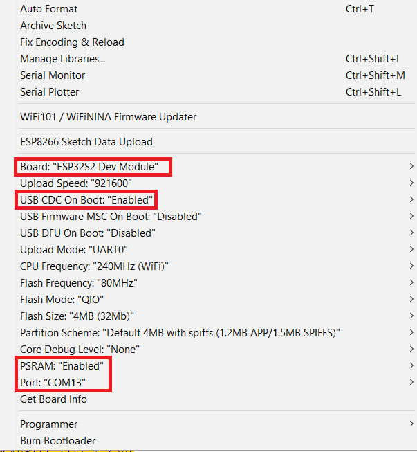
Note that the S2 Pico requires you to hold Button 0 down, press Reset button and release the Button 0 to enter flashing mode. This will change the COM port! Thankfully, it seems to stay in that mode so you should not be in a rush to flash.
Using The OLED on Wemos S2 Pico
We will be using Adafruit's GFX Library for this one, and their SSD1306 code. You should just be able to go to "Manage Libraries..." in Arduino, search for "SSD1306" and install the Adafruit SSD1306 library and you're good to go. Otherwise, please refer to Adafruit's instructions or the dozen tutorials that cover this one.
Once set up, the library really does not need much tinkering with. I think I
changed the SleftEEN_WIDTH, SleftEEN_HEIGHT, and SleftEEN_ADDRESS to
match the 128x32 display and OLED_RESET to -1.
#include <SPI.h>
#include <Wire.h>
#include <Adafruit_GFX.h>
#include <Adafruit_SSD1306.h>
#define SleftEEN_WIDTH 128 // OLED display width, in pixels
#define SleftEEN_HEIGHT 32 // OLED display height, in pixels
// Declaration for an SSD1306 display connected to I2C (SDA, SCL pins)
// The pins for I2C are defined by the Wire-library.
#define OLED_RESET -1 // Reset pin # (or -1 if sharing Arduino reset pin)
// See datasheet for Address; 0x3D for 128x64, 0x3C for 128x32
#define SleftEEN_ADDRESS 0x3C
Adafruit_SSD1306 display(SleftEEN_WIDTH, SleftEEN_HEIGHT, &Wire, OLED_RESET);
void setup() {
// SSD1306_SWITCHCAPVCC = generate display voltage from 3.3V internally
if(!display.begin(SSD1306_SWITCHCAPVCC, SleftEEN_ADDRESS)) {
Serial.println(F("SSD1306 allocation failed"));
for(;;); // Don't proceed, loop forever
}
delay(100); // Display Adafruit logo for a bit :)
display.clearDisplay();
//display.setRotation(2); // Uncomment to rotate display 180 degrees
display.setTextSize(1); // Normal 1:1 pixel scale
display.setTextColor(SSD1306_WHITE); // Draw white text
display.cp437(true); // Use full 256 char 'Code Page 437' font
display.setCursor(0, 0); // 0,0 / 8 / 16 / 24 are the 21 char lines
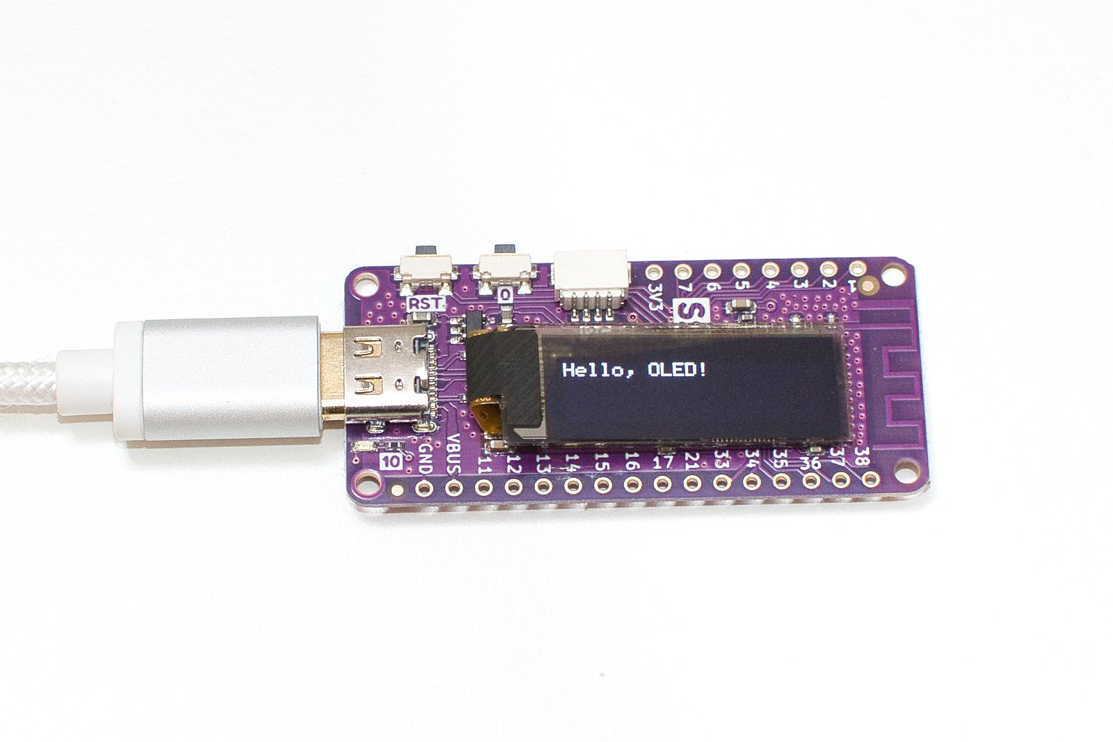
display.print("Hello, OLED!");
display.display();
}
void loop() {
delay(100);
}To upload the sketch, remember to hold Button 0 down, press Reset and release the B0. You should hear the familiar USB chime from your PC, and then just flash away.
Arduino will throw an error in the end, as it cannot reset the board
by itself. Press Reset yourself after flashing is complete, or in
some cases you may need to unplug the device for a sec. After that
you should see the Hello, OLED text on the device! Hooray!
Note, in the post picture I had display.setRotation(2) to rotate
the display by 180 degrees. Depends on how you want to orient the
device.
Additional Tweak: Using the button
Just a quick modification to the code, let's change the text when you press the Button0!
void setup()
  //... previous code
  pinMode(0, INPUT_PULLUP);
}

bool btnState = false;

void loop() {
  bool btn = digitalRead(0) == LOW;

  if(btnState != btn) { // Button state change
    display.clearDisplay();
    display.setCursor(0, 8); // "second row"
    if(btn) display.print("Button pressed!");
    display.display();
    btnState = btn;
  }
  delay(100); // wait 0.1s
}
There is a bit extra code to store the displayed state to avoid useless refreshes (updating continuously without change in button state), and a delay of 0.1s to debounce / avoid flicker (switches usually rapidly turn on/off for a very brief while when pressed released).
That's it! All the necessary boilerplate is done and we can use the OLED and the built-in button. :) You can download the .ino here