Just a quick update this time: A long while ago I made a post about using Adafruit Trinket without Arduino and later converted that into a TrinketMIDI Github repository for making a MIDI device with ATtiny:
Now thanks to a contribution by Gerhard Zintel, there is now also a MIDI volume device sample code in the repo. If you want to make a MIDI volume controller, it should be pretty easy with the code as well. Enjoy!
Note: The keyboard and keycaps in this article are bought by me and not a review sample. I have, however worked with KeyboardCo in the past and like them a lot in general. But just so you know!
A new keyboard in the house! Namely the Filco Majestouch-2 TK (MX Blue) Always an exciting happening in the family. After typing happily for a couple of years with superbly compact and slim Apple Magic Keyboard (works fine with Windows btw.) at home, and with my Topre Realforce 88UB at work, I thought it would be fun to get a keyboard with the classic clickly MX blues.
My main reason to get Cherries apart from the amazing blue clicky sound is the fact that one can get a wide selection of custom keycaps, very much unlike the Topre ones where you’re pretty much stuck with the keys they came with, or maybe some with Japanese characters.
After some consultation in Geekhack, I decided that out of the options I had available (in Finland pretty much zero apart from some gaming keyboards), Filco would be a good choice. Knowing they stock it, I headed straight to The Keyboard Company website and after some deliberation opted for one in Scandinavian layout — easier to swap here in Finland if I want to switch again. The Filcos are in no way inexpensive, but knowing the amount of time I spend typing, I considered the hourly cost to be quite reasonable.
Unboxing Filco Majestouch
The delivery from KeyboardCo arrived promptly as always, and I decided to shoot a classic unboxing video. Notice the great “Code and Life” logo in the thumbnail! There are no audio comments in the video, but you can hear the clickies quite well.
As an “out of the box” experience, here are my major plusses and minuses list:
Plusses
Very solid build, the case will definitely last a lifetime
Great MX blue typing experience and satisfying sound
Compact layout, it doesn’t expand much outside the keys in any direction
It’s a “no frills” workhorse, not much more to be said!
Minuses
Standard keycaps are quite high, making a wrist support pretty much a must
There’s nothing particularly exciting or special about they look
I started writing another blog post about my new keyboard today, and when uploading the unboxing video to my YouTube channel, I realized they have no “auto white balance” option, not in their new or old video editor either. Shoot. After googling for free video editors, I settled on OpenShot.
And guess what? OpenShot doesn’t have a white balance setting either! The author himself said this on Reddit, asking for help to implement it. I was pretty shocked, as it seems like the first filter I would implement myself, and thought “surely it doesn’t take more than five minutes to implement one, right?”. So I did. Well, it took maybe 15 minutes, plus 45 fiddling with Jupyter notebooks to get PIL and numpy commands right.
The Python 3 code above basically loads an image (either local if you run it with Jupyter notebook locally, or over network), get a small subportion of it to act as a grey reference, and adjusts color channel balance with two alternate methods: RGB or YCbCr. More advanced versions should be easy to add as well.
You can view the above gist in Github or just copy-paste the code to your own / cloud based notebook to try it out:
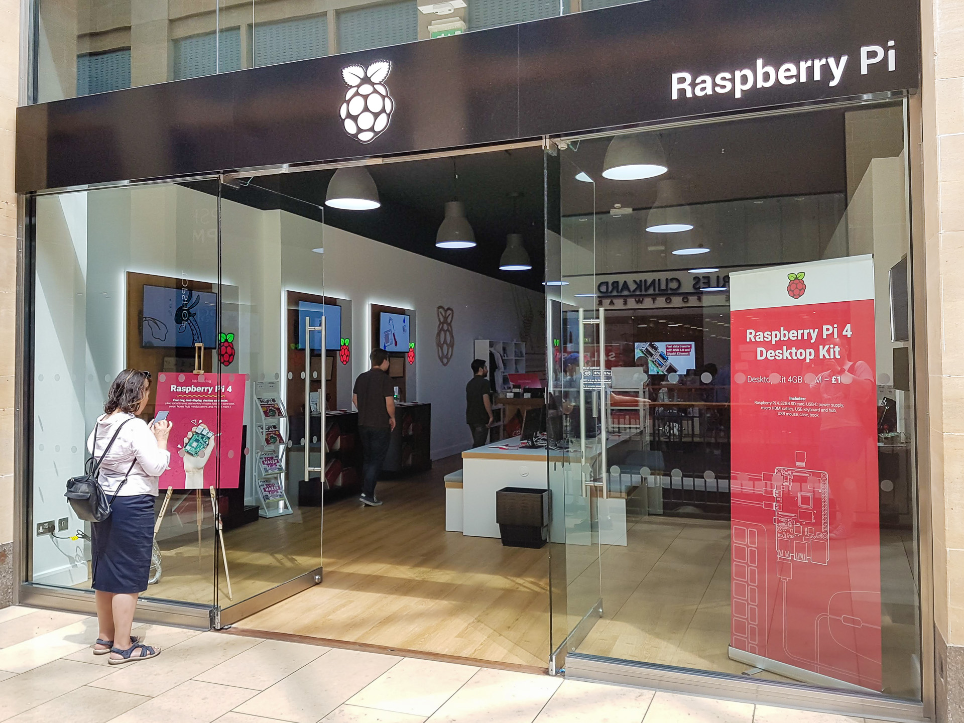
Two weeks ago I had the chance to visit the official Raspberry Pi store in Cambridge. Apart from those living in the UK, I think not many will it that far, so I thought to share my pictures from the visit for you to enjoy (and maybe evaluate whether it’s worth the trip). Enjoy!
The Store
The Raspberry Pi Store is located in the Grand Arcade shopping mall, and on the second floor. Looks nice and official.
Naturally, it houses an excellent selection of the Pi boards. There was 3B-, 3A2, Zero, Zero W, Zero W+, compute modules, Pi 4 of course (with different memory options), all with good availability. To cheapest Zero boards were limited to 1 per customer, much like in web store. All boards had a good choice of cases as well on sale. Very nice.
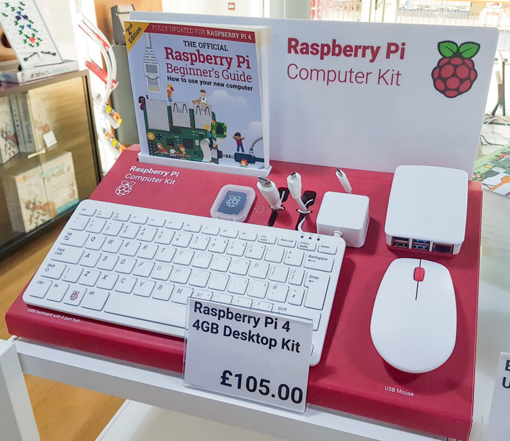
You could also get whole computer kits with a nice raspberry themed keyboard and mouse, as well as a case, an SD card, power delivery (UK plug at least on the display version) and a beginner’s guide. Nice combo, although it of course about doubles the price tag of just the unit itself.
The dual monitor capability of the Pi 4 was very much on display, and there were a couple of machines to try out in the central table area of the store. The machines also had network connection, which was nice for test drive purposes, and not something that even mainstream computer stores have.
Tired of reaching for that power button? Or perhaps you’d like to be able to turn on your PC when travelling? I sometimes like to do that to access some local files (or software via VNC), but dislike leaving the PC on for days “just in case”. This article explains how you can do it with the $3.50 Wemos D1 mini.
Wake-on-LAN is of course a great idea, but it only works if your PC is physically wired to the router. Wake-on-WLAN theoretically should work for WLAN as well, but here’s a shocking revelation: it usually does not, as it requires your PC to power up your WLAN card for it to receive the magic WLAN packet, and router support. At least I’ve never had a combination of network card and router that would work.
I used to have a nice DIY knock-sensor to PS/2 thingy, but the piezo kept dropping out, and got tired of repeating the required sequence of knocks. So I thought it would be cooler to have just a Bluetooth button I could use to do the same. I had a WLAN enabled Wemos D1 mini board lying around, and it only draws less than 100 mA of power, so I thought to find out if I could make it listen to a “magic packet” and boot up my PC. Turns out it was easier than I even thought!
Note that this project involves opening your PC case and playing around with your motherboard power switch wiring. Everything should be relatively hard to screw up, but if done wrong, you may get electrocuted, you may stick a screwdriver where it shouldn’t go and damage your motherboard or other components, so proceed with your own risk!
Time for something completely different from my usual electronics projects. This morning I started to wonder (don’t ask why) a couple of fundamental questions:
If you’d convert the planet Mercury to a huge solar panel, would it cover the sun as viewed from earth?
How large portion of sun’s energy you’d get for the project if you started by covering the surface of Mercury with solar panels?
Assuming hyper advanced technology that could do this, would Venus or some other planet in our solar system perhaps be a better target?
The thought experiment initiated from some Science podcast, probably from Anatomy of Next scientist interviews (or BBC’s Tomorrow’s World), which talked about turning Mercury into solar panels or mirrors — essentially a Dyson Swarm.
Mercury is close to sun, so it’s a clear candidate, but I started thinking “If you were an alien (or future human race) with super advanced technology arriving to solar system, which planet would you pick?”. You could of course harvest gas giants for Helium-3 and use fusion energy to do stuff, or have some not-yet-invented energy source. But let’s focus on the giant fusion reactor in the center of our solar system, and look at some numbers.
Basic Data for Planets
If we think of sun as a perfect sphere putting out energy in form of solar radiation to pretty much uniformly to all directions, the amount of radiation reaching a certain planet is a simple function of the planet’s radius and it’s distance from sun (π*r^2 / d). Surely you can quickly google which planet gets the most radiation? Turns out most articles on the internet for laymen focus on energy per unit of area (square feet or meters), and leave out the size of the planet completely. Well, easy to fix! Let’s start with some basic data from NASA’s planetary factsheet:
Planet
Mass (10^24kg)
Diameter (km)
Distance from Sun (10^6 km)
Mercury
0.33
4,879
58
Venus
4.87
12,104
108
Earth
5.97
12,756
150
Mars
0.642
6,792
228
Jupiter
1898
142,984
779
Saturn
568
120,536
1,434
Uranus
86.8
51,118
2,873
Neptune
102
49,528
4,495
Pluto
0.0146
2,370
5,906
How Big Do Planets Look From The Sun?
Now as all planets are really far away from the sun compared to their radius and diameter, I’m just doing a shortcut and calculating their angle from sun as just the ratio of diameter and distance, owing to the fact that sin(x) ≈ x for very small values of x (second coefficient of Taylor series expansion is x^3/9 so with these numbers we’ll get about 20 significant digits correct). Calculating diameter/distance shows that even the largest planet from the sun, Jupiter, is just 184 microradians, that is 0.000184 radians wide when viewed from the sun! Full sky would be 3.14 radians, so there’s some way to go!