MIDI to USB Adapter with Teensy LC
Among my recent electronics purchase spree was the amazing Teensy LC from PJRC. It has a nice ARM Cortex-M0+ processor, real hardware USB, and what’s the nicest part, an Arduino add-on called Teensyduino which enables easy programming with Arduino, but with support for many of the hardware features.
Now I started playing piano a while ago, and just a few weeks ago bought a Pianoteq license to send notes via MIDI to my computer, and render high quality piano sound to speakers. However, it turns out my $8 USB-MIDI adapter from DealExtreme had a less than perfect implementation, essentially changing pedal events into “note on” events!
Thankfully, I had a MIDI connector and a high-speed optocoupler at hand, and with these I could implement a MIDI in rather easily. After some investigation with Arduino Uno, it seemed quite simple to receive the serial MIDI bytes and dump them over Arduino serial (I’ll write another post about this later).
However, Arduino cannot become a USB MIDI device very easily, so here comes the really nice part: Teensy LC can, and the Teensyduino add-on included a working USB MIDI and also serial MIDI libraries!
The Hardware
The Wikipedia page for MIDI essentially shows the required circuitry for receiving MIDI data – wire the DIN cable pins 4 and 5 through the receiving side of optocoupler and put a 200 ohm resistor in series with it. A diode is also suggested for reverse current (ESD) protection, but I skipped that. You can start with a LED instead of optocoupler to see it lights up if you’re unsure you have pins 4 and 5 the right way. Or just put the LED (with a resistor) on the other side of the optocoupler first.
The HCPL-2531 I had at hand requires an additional VCC connection on the sending side. After some experimentation, a 4k7 ohm pullup resistor between VCC and VO1 (NPN-transistor base?) gave the cleanest signal out. The wiring diagram (thanks Diptrace!) is shown below:
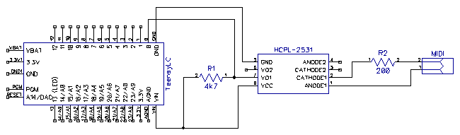
As you can see, only a Teensy LC, the optocoupler, two resistors (220 ohm for the MIDI side, 4k7 for the Teensy side transistor load resistor) and some wire is needed. Talk about simple! Below you can see a pictorial representation of the above diagram:
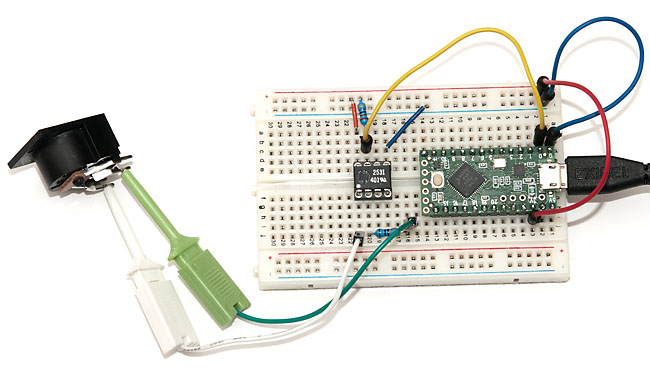
So essentially the circuit has (HCPL 2531 part on the left for reference):
- Teensy LC “G” and “3V” pins wired to GND and VCC rails of the breadboard
- Optocoupler pin 8 (VCC) to VCC rail
- Optocoupler pin 7 (VO1) to VCC via 4k7 ohm resistor
- Optocoupler pin 7 (VO1) also wired to Teensy LC pin “0” (serial RX)
- Optocoupler pin 5 (GND) to GND rail
- Optocoupler pin 1 (ANODE1) to PIN4 (I think) of the MIDI DIN connector
- Optocoupler pin 2 (CATHODE1) to PIN5 (I think) of the MIDI DIN connector via 220 ohm resistor
- USB cable to computer
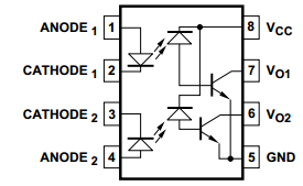
That’s really it! Depending on the exact type and model of the optocoupler, the wiring may be a bit different, but not much. If you have a different model and are not sure how the pins work, I suggest first making some tests with LED’s on both sides and a multimeter (or oscilloscope preferably) to see how the signal is transmitting over the optocoupler.
The Code
UPDATE 2025 I noticed the example below also requires you to enter Tools .. Manage Libraries... in Arduino and install the MIDI library by Francois Best which can be found under "Contributed" type and "Communication" topic (just search for "MIDI").
Now comes the easy part. Just plug the Teensy into computer, run Arduino (with the Teensyduino add-on installed), change Teensy USB type to “MIDI” (see Teensyduino USB MIDI for examples which you can run first), and program the following sketch:
/* MIDI to USB adapter - for use with Teensy or boards where Serial is separate from MIDI
 * As MIDI messages arrive, they are sent as USB midi messages. Only transmits note on,
 * off and pedal (control change) events.
 *
 * Note that this does not work on a regular Arduino boards (no separate USB and UART)!
 *
 * Based on Francois Best midi library example:
 * http://arduinomidilib.fortyseveneffects.com/
 * This example code is released into the public domain.
 */

#include <MIDI.h>

// The 2 lines below added in 2025 as per https://github.com/FortySevenEffects/arduino_midi_library
// Create and bind the MIDI interface to the default hardware Serial port
MIDI_CREATE_DEFAULT_INSTANCE();

void myNoteOn(byte channel, byte note, byte velocity) {
  usbMIDI.sendNoteOn(note, velocity, channel);
}

void myNoteOff(byte channel, byte note, byte velocity) {
  usbMIDI.sendNoteOff(note, velocity, channel);
}

void myControlChange(byte channel, byte number, byte value) {
  usbMIDI.sendControlChange(number, value, channel);
}

void setup() {
  MIDI.setHandleNoteOn(myNoteOn);
  MIDI.setHandleNoteOff(myNoteOff);
  MIDI.setHandleControlChange(myControlChange);
  MIDI.begin(MIDI_CHANNEL_OMNI);
}

void loop() {
  MIDI.read();
}
That’s really it! With this sketch, I can just plug my MIDI keyboard into the DIN connector via cable, and plug the Teensy into my MacBook, and both my playing and pedal action get nicely transmitted to the computer. Not bad for $20 worth of components and some 20 lines of code!
Spoilers ahead! A similar MIDI to USB adapter can be implemented with Arduino and some additional software on computer side (serial to MIDI bridge). And as of today, I have also managed to achieve native USB MIDI with ATmega328p and V-USB library, which means you could reprogram any small Arduino-compatible device (including Pro Trinket from Adafruit). Stay tuned for additional posts detailing these hacks. :)