***Update 2025: I've had more trouble with this fish binding than it is worth. I've crippled my fish shell irrecoverably a couple times and had numerous issues trying to adapt for bash and zsh. I am keeping this post for reference, but I would strongly advice using a proper agentic tool nowadays with some guardrails. ***
Read on if you want to read about my journey to make fish transform comment lines to runnable commands.
After a bit of AI hiatus, I noticed that llama 3.0 models were released and wanted to try the models. Sure enough, after a week the weights we re available at the official site. However, the Docker image hasn't been used in a while and I wanted to upgrade it without losing the models.
There was almost no information on this available online yet, and even the
ollama docker documentation is quite non-existent — maybe for seasoned
Docker users it is obvious what needs to be done? But not for me, so let's see
if I can manage it.
Upgrading the docker image
First, let's just upgrade the ollama/ollama image:
$ sudo docker pull ollama/ollama
This is nice, but the currently running container is still the old one. Let's stop it:
$ sudo docker stop ollama
Checking the location of the files
I remember I set a custom directory to store the models. Let's check where it is:
As can be seen, the models are stored in /mnt/scratch/docker/volumes/ollama/_data. Let's make a hard-linked copy
of the files into another folder, to make sure we don't lose them:
$ sudo bash$ cd /mnt/scratch$ cp -al docker/volumes/ollama/_data ollama_backup
Now that we have the models backed up, let's remove the old container:
Continuing the awesome and not so unique stream of ideas on what to do with
ChatGPT, here's a bit modified take to my previous post on self-running ChatGPT generated Python code.
This time, let's do a shell script that takes a description of what you want as a shell command, and returns just that command. Here's how it will work:
$ shai find latest 3 files46 total tokensls -lt | head -n 3$ ls -lt | head -n 3total 1233-rwxrwxrwx 1 root root 5505 huhti 4 2023 python-chatgpt-ai.md-rwxrwxrwx 1 root root 10416 maalis 26 2023 golang-sveltekit-chatgpt.md
As seen, this time I'm not running the command automatically, but just returning the command. This is a bit safer, as you can inspect the command before running it. The script is quite simple:
#!/usr/bin/env pythonimport sys, osfrom openai import OpenAIfrom configparser import ConfigParser# Read the config file openai.ini from same directory as this scriptpath = os.path.dirname(os.path.realpath(__file__))config = ConfigParser()config.read(path + '/openai.ini')client = OpenAI(api_key=config['openai']['api_key'])prompt = ' '.join(sys.argv[1:])role = ('You are Ubuntu linux shell helper. Given a question, ' 'answer with just a shell command, nothing else.')chat_completion = client.chat.completions.create( messages=[ { "role": "system", "content": role }, { "role": "user", "content": prompt } ], model = config['shai']['model'])print(chat_completion.usage.total_tokens, 'tokens:')print(chat_completion.choices[0].message.content)
I decided GPT 3.5 Turbo is a good model for this, as it should be able to handle shell commands quite well. You also need to have a openai.ini file in the same directory as the script, with the following content:
I previously covered how to run your own ChatGPT script with Python and Golang. But what if you want to create a script that automatically runs the ChatGPT generated code? That is what I will cover in this post. The idea is really simple:
Create a script that asks for user input
Pass the input to ChatGPT
Run the ChatGPT generated code
NOTE: Please read the caveats at the end of the post before using this!
Calling The OpenAI API
First step is simple, just call the OpenAI API with the user input. If "-v" is given as the first argument, print the raw answer and usage statistics as well.
#!/usr/bin/python3import openaiimport sysopenai.api_key = 'sk-xxx'verbose = sys.argv[1] == '-v'prompt = ' '.join(sys.argv[2 if verbose else 1:])resp = openai.ChatCompletion.create( model="gpt-3.5-turbo", messages=[ {"role": "system", "content": "You are Python code generator. Answer with just the Python code."}, {"role": "user", "content": prompt}, ])data = resp['choices'][0]['message']['content']if verbose: print(data, 'Usage was:', resp['usage'], sep='\n')
Parsing the Code From Response
A rather simplistic implementation looks for set of start tokens and end tokens and returns the code between them. This is not perfect, but it works as long as the ChatGPT response does not contain multiple code blocks.
OpenAI came out with ChatGPT, and wow, that is quite something. What is also remarkable is the
load the ChatGPT client is under, and how often it is "experiencing high demand".
Or just requires you to prove you are human and log in again.
You can get ChatGPT Plus for $20 a month, but hey, you can also get chat experience for $0.002 per 1000 tokens. To hit that monthly fee, you need to use 10 M tokens, which is not that far from 10 M words. That is pretty heavy use...
Using OpenAI ChatGPT (gpt-3.5-turbo) through Python API
To use the ChatGPT API, at its simplest form with Python3 you just pip install openai and create a short script:
#!/usr/bin/python3import openaiimport sysopenai.api_key = 'sk-yourkeyhere'if len(sys.argv) < 2: prompt = input('Prompt: ')else: prompt = ' '.join(sys.argv[1:])resp = openai.ChatCompletion.create( model="gpt-3.5-turbo", messages=[ {"role": "system", "content": "You are a programming expert giving advice to a colleague."}, {"role": "user", "content": prompt} ])print(resp['choices'][0]['message']['content'])print('Usage was', resp['usage'])
You need to create credentials at OpenAI platform, enter your credit card and set a warning and hard treshold for monthly billing (I set mine to $4 and $10, respectively). But after filling your API key to the script, you can just run it:
$ python3 chat.py What is the capital of AlaskaThe capital of Alaska is Juneau. However, I believe you were looking for programming advice. What specifically are you working on and what kind of advice are you seeking?Usage was { "completion_tokens": 34, "prompt_tokens": 30, "total_tokens": 64}
Now that is pretty nice, but we can do better!
Golang client with SvelteKit frontend
In my previous Golang+SvelteKit GUI post I explored how to create a Go application acting as a web server and making a user interface with SvelteKit:
Golang has high performance and excellent set of libraries to accomplish many tasks
Cross-platform support out of the box with compact executables
SvelteKit is fast to develop as a frontend, requiring very low amount of code for rich interactive UIs
OpenAI does not produce it's own Go library, but that API as well documented and shabaronov has made an excellent Golang OpenAI API library that makes calling the API simple. It even supports GPT4, so if you have access to that, you can create a GPT4 chat client as well.
Without further ado, here's the Github repository for my GoChatGPT client. You can basically git clone://github.com/jokkebk/gochatgpt and follow the instructions in README.md to get it running, it's about 4 commands all in all.
Let's look a bit what the code does!
Golang ChatGPT Backend
Main method of the backend is nothing too complex:
Serve the SvelteKit GUI from static folder (including index.html when user requests /).
Have a chat endpoint at /chat that takes a JSON object with chat messages and passes it to OpenAI API.
Return the OpenAI [ChatGPT] response as a string to calling client.
Compared to Arduino Uno, the RP2040 has major advantages for this project:
Much higher clock frequency of 133 MHz means there's cycles to spare even at ~1 Mhz rates
Relatively vast SRAM memory, 264 kB vs. 2 kB
Native C SDK that is rather easy to work with
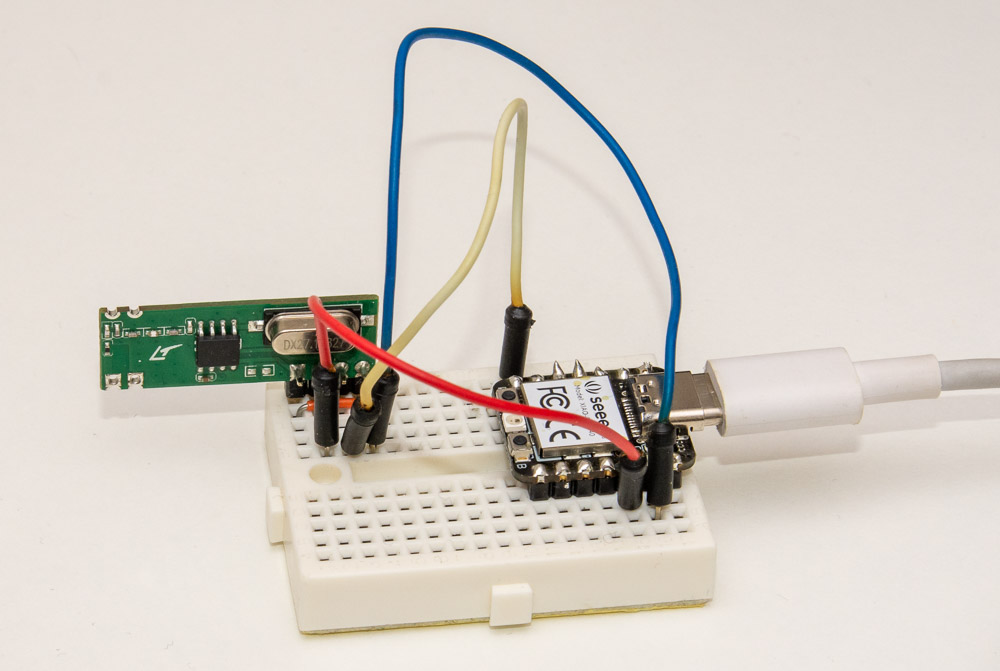
I'm using the Seeed XIAO RP2040 for this project. It is extremely compact and has a nice USB-C interface. You can see the wiring, it's just 3.3V and GND to the receiver (which luckily did work fine with that voltage) and signal to GPIO pin 0.
Note that while RP2040 pinout has 5V supply line, the GPIO pins are not 5V tolerant, so you should not power a 5V receiver and directly connect it to pin 0. A voltage divider is strongly recommended to avoid longer term damage to the RP2040 pin.
Setting up RP2040 programming environment
I basically followed the Getting started guide that was linked from the Pico SDK Github to get the Blink example working. After that, it was quite simple to set up a new project following the "Quick-start your own project", setting up CMakeLists.txt like this:
cmake_minimum_required(VERSION 3.13)# initialize the SDK based on PICO_SDK_PATH# note: this must happen before project()include(pico_sdk_import.cmake)project(joonas-pico)# initialize the Raspberry Pi Pico SDKpico_sdk_init()# rest of your projectadd_subdirectory(logic_analyze)
$ mkdir logic_analyze$ cd logic_analyze$ wget https://codeandlife.com/images/2023/logic-analyze-pico.zip$ unzip logic_analyze-pico.zip$ mkdir build$ cd build$ export PICO_SDK_PATH=../../pico-sdk$ cmake ..$ make
Note that this assumes you placed the example directory logic_analyze alongside your pico-sdk directory.
After running make, you should find the logic.uf2 file under logic_analyze directory and you can just drag and drop it to your RP2040 when it is in USB drive mode.
C Code for Recording GPIO Changes
The code is basically combination of what I did for Arduino and Raspberry Pi, and the hello_gpio_irq and hello_timer examples. Basic logic:
Setup stdio_init_all() (over USB, necessary definitions to enable that in CMakeLists.txt file) and wait until stdio_usb_connected() returns true.
Loop forever, asking the user over serial (USB) to press a key to start recording
Clear receive buffer
Set alarm timeout of 5 seconds to end recording if buffer hasn't been filled
Set up GPIO interrupt triggers on rising and falling edges of pin 0
In the interrupt handler, record time elapsed since last edge using time_us_64()
Once timeout is reached or buffer has been filled, disable GPIO interrupt and print out received timings.