I recently got myself a mechanical keyboard (to be precise, a Happy Hacking Keyboard Professional 2). One side effect of this switch was, that the new keyboard no longer works with simple passive PS/2 adapter. And the only type of input my current motherboard can be configured to power up on is spacebar from a PS/2 keyboard.
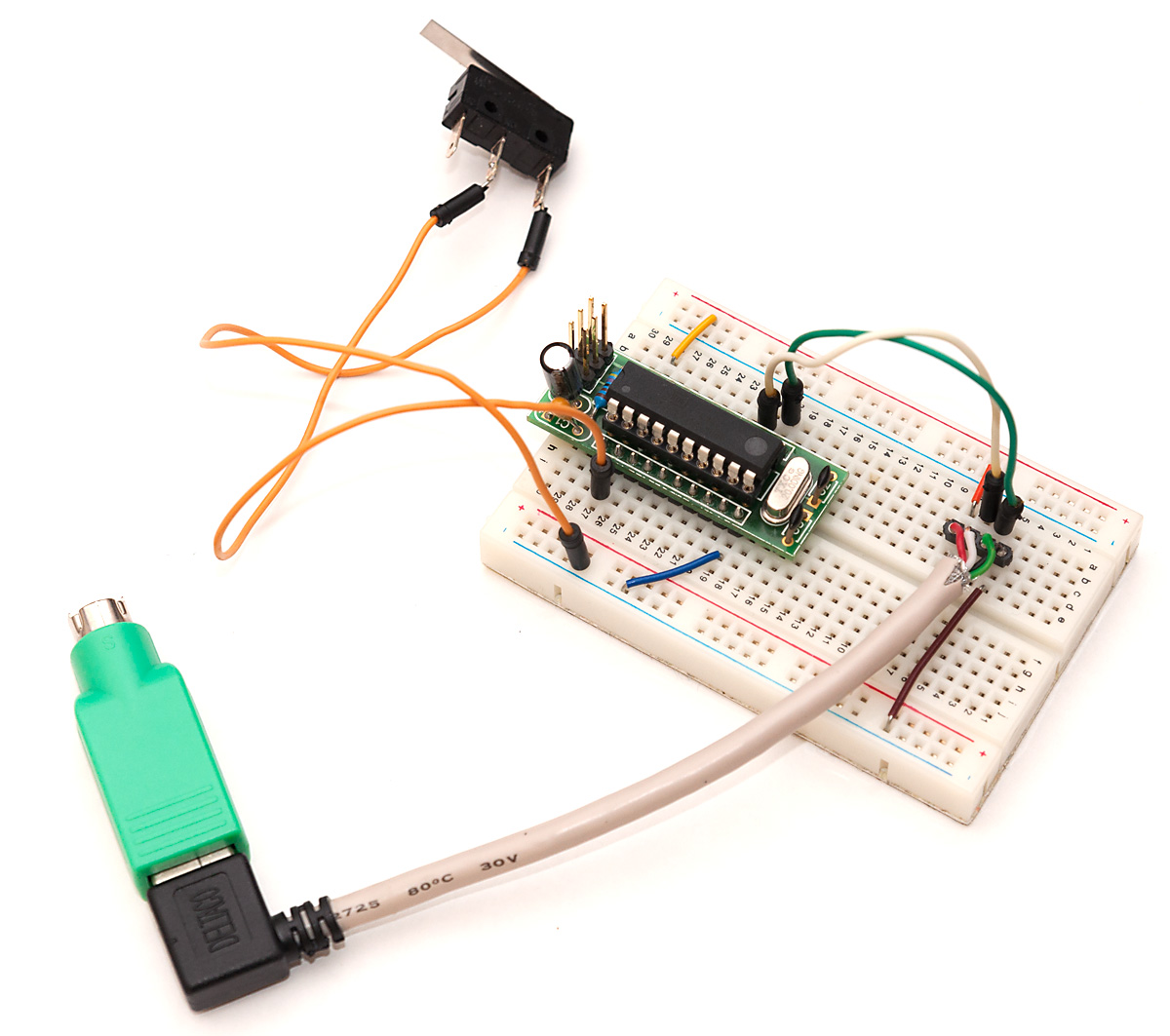
Well, I had read from somewhere that PS/2 protocol is not too complex, so I decided to find out if I could make a simple gadget that would send spacebar keypress over PS/2 when a switch was toggled. That turned out to be quite easy (with some limitations, read the end of this post to find out more).
PS/2 basics
The Wikipedia page for PS/2 connector already looked promising – there are GND and VCC pins straight available, and only two additional (open collector type) lines are needed for data and clock lines. Communication is bi-directional with the keyboard providing clock signal and sending end toggles data line while the receiving end listens.
Open collector basically means that the lines have a pullup resistor to VCC, and either end (PC/keyboard in this case) can pull the data line low while the other end monitors the data line. Because only active action either end can take is to pull the line low, no contention between the two ends can happen so there’s no need to be certain that the other end isn’t trying to pull line up while you’re pulling it down (which may easily end up with some overloaded MCU pins).
Since my V-USB tutorials became popular, a recurring theme in the comments section have been people who are obviously motivated to try out the tutorial, but due to limited exposure to C language and command-line are either having trouble following my short instructions to compile the example .hex files, or being scared of the command-line, have tried to use AVR Studio instead, and fail.
I have to admit that first I was a bit annoyed by these people – why are they trying to follow a challenging project, when they seemingly have no understanding of how command line, makefiles, C compiler and linking process works? Then, comment by comment, I finally realized that not everyone started coding in the nineties where you launched Windows 3.11 mostly to play Solitaire, and biggest thing in coding productivity was 80×50 text mode which allowed you to have 16-color hacking bliss in your Borland Turbo C++ 3.0 IDE (or RHIDE, after DJGPP came around).
So, instead of either ignoring these people, or spending any more hours answering the same questions, I decided to start a new series of tutorials to cover really basics of getting into AVR development the way I like to do it: Old skool.
Navigating the command line
The bar for command-line wizardry in AVR development is low. There are four levels in it:
Firing up command prompt
Navigating to a directory and viewings its contents
Running commands
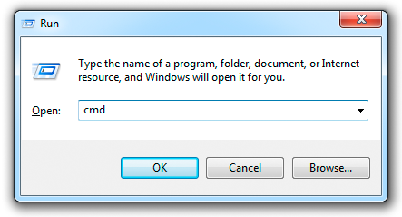
The first one is really easy. In Windows 7 you can just click the start button, type “cmd”, and you’re there. Or type “command”, as the Command Prompt is usually the first search hit displayed. More hardcore persons use Win+R (that key with flag symbol finally does something useful!) and type “cmd” into the Run dialog as shown in title image of this post.
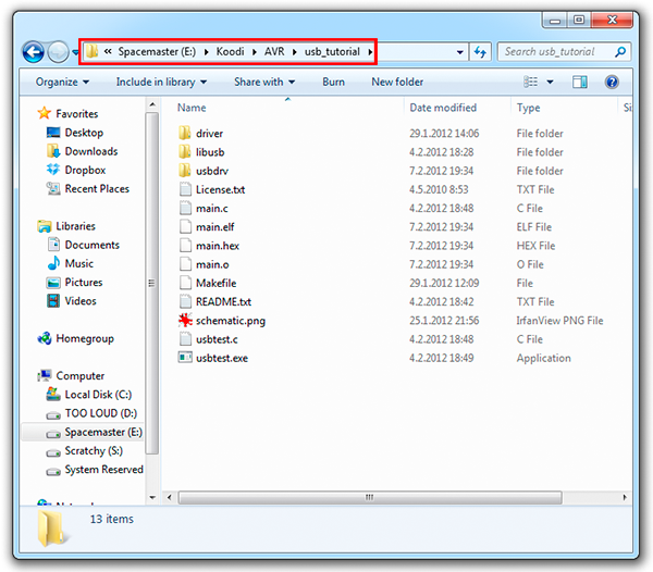
Once you’ve bitten the blue pill, commanding #2 is also quite easy. First, you need to understand that command prompt is very much like Windows explorer (shown in the above screenshot) – you are always in some directory, and the commands you enter usually work within that directory. In the example above, we are in directory E:\Koodi\AVR\usb_tutorial – let’s try if we can replicate that in command line:
As a continuation to my Raspberry Pi and Arduino communication post, I thought I’d do the same but opposite way. This time, I thought it would be nice to make a proper Arduino library to make the process more streamlined.
To make communication more robust, I decided to implement a more formal communication over serial to enable applications that have some idea if a command sent to Arduino was successfully carried out or not, and also introduce basic error recovery if invalid commands or wrong number of parameters are received.
I wanted to make a simple formal protocol to send commands and hex, byte or word-sized parameters related to that command over serial line to the Arduino. For the protocol, I had these requirements:
Text-based, so communication can be emulated with Arduino IDE’s “Serial Monitor” tool
Size-efficient to speed up communications with slow baud rates
Support for at least a few dozen commands and free number of parameters
Success and error messages from Arduino
Capability to return to known state after invalid commands, invalid number of arguments, communication errors or breakdowns
After some consideration, I chose to select non-overlapping sets of symbols from the ASCII character set for commands, parameters, control characters and success/error messages:
Small letters (a-z) for commands (26 should be enough for everyone, right?)
Numbers 0-9 and capital letters A-F to send parameters as hex-encoded values
Newline to mark end of command and parameters (either ‘\r’ + ‘\n’ or just ‘\n’)
Capital letters O, K, and R for success (OK) and error (RR) indications
With non-overlapping characters used for different things, detecting errors in sent commands becomes easier, as any “non-expected” character marks an error situation and as status messages OK and RR do not appear in commands, implementing two-way communication (commands to both directions) is easy later on.
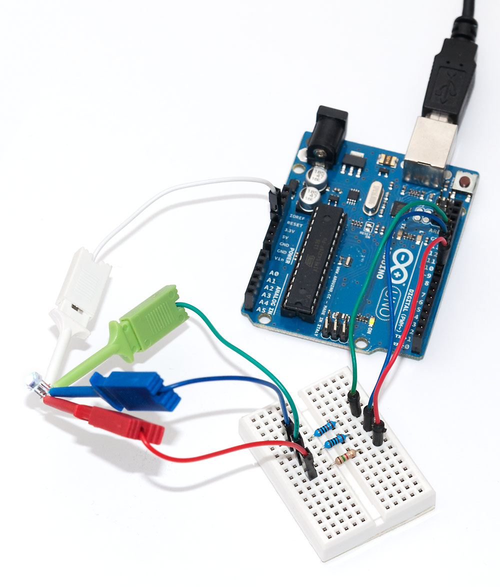
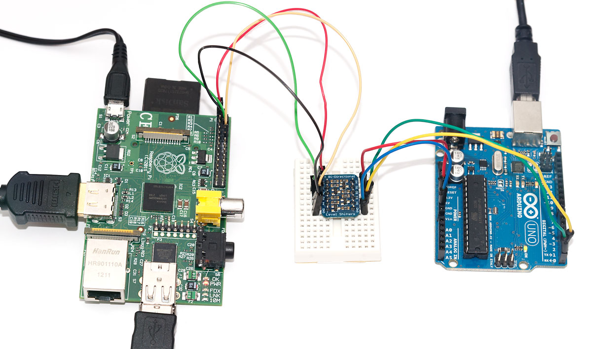
Merry Christmas to everyone! Today’s hack is something that I’ve been planning to try out for a while: Using the Raspberry Pi as a (relatively inexpensive) “HDMI shield” for the Arduino microcontroller. While the Pi can easily do most things that the Arduino can and usually much more, one might have an otherwise complete project (for example, something related to home theater automation) that would benefit from HDMI output.
Arduino display shields are not the least expensive, so why not use a RaspPi instead? There have been hacks for using RaspPi as network shield, too, and this project is very much like it (actually, you could change the Pi-side code just a bit and have some network-related commands available for your Arduino in no time).
The basic hardware premise for this hack is very straightforward – wire the Pi and Arduino together using the serial interface available on both. Because Pi is 3.3V and Arduino 5V, a level converter is needed – I used one from Adafruit this time, as it’s dead simple to use and doesn’t pose the dangers of overloading Pi like my simple resistor option does (you might, however, check that link out as it contains the pinouts for RaspPi serial pins in the GPIO header).
On software side, the Pi acts as a “server”, taking simple display commands via serial link. You could even start the Pi server script and connect to the serial port with Putty, and the session could look a bit like the following:
# initialize viewport - not actually implemented yet
init 500 500
# draw a 10x10 rectangle at (5,15)
draw 5 15 10 10
# exit the server
exit
The python server uses pyserial for serial communications, currently at 9600 bps, but the Pi and Arduino should be able to do 115 200 as well. For graphics, pygame framework is used. Current version of code initializes a 500×500 pixel graphics viewport, but one could use the parameters given by “init” command from Arduino side to define that, too. The code should be rather straightforward to understand: there are only two supported commands, “draw” with four parameters, and “quit” to exit the otherwise infinite loop waiting for draw commands (I named the file ar2pi.py):
#!/usr/bin/env pythonimport serialimport stringimport pygameser = serial.Serial("/dev/ttyAMA0",9600)ser.open()pygame.init()window = pygame.display.set_mode((500, 500))colour = pygame.Color("blue")pygame.mouse.set_visible(False)quit = Falsewhile not quit: line = ser.readline() words = line.split() if words[0] == "rect": pygame.draw.rect(window, colour, (int(words[1]), int(words[2]), int(words[3]), int(words[4]))) elif words[0] == "exit": quit = True pygame.display.flip()ser.close()
The WebFaction web server hosting Code and Life (and other my sites) has been experiencing filesystem issues and has been down for fscking several times. Apologies for site readers, hopefully the provider gets these glitches ironed out soon.
As I mentioned earlier, I got a PicoScope 3206B back in August. After a few months of use I have gathered enough experience with it to feel qualified to write a review on the device.
Those who haven’t yet done so, I suggest you to check out my earlier review of PicoScope 2204 – it covers a bit of my rationale for a USB scope, and the basic features of Picoscope software, which is the same for the whole PicoScope product line.
The 3206B is the top-of-the-line two-channel scope in the 3000 series. The prices have dropped a bit after the introduction of mixed signal version 3206B MSO, so for $1320, you’ll get this device with fairly impressive key feature set:
Two channels, and external trigger line
200 MHz analog bandwith
500 MS/s sampling rate
A huge 128 MS sample buffer
Arbitary waveform function generator (20 MS/s)
Two 250 MHz probes, storage bag and software CD
For full details, I suggest you to look up the 3200 series spec sheet from Picotech’s website. Let’s get started!
Unpacking the box
Picotech ships from UK and within EU, no additional taxes or import fees need to be paid. Both my deliveries from them have arrived promptly within two days, well packaged and in impeccable condition.
The scope comes in a cardboard box that also has space for the probes, a storage bag and software CD. Nothing too fancy, but works well for longer term storage, too.