I made a big step in coding geekdom this summer by upgrading the most low-level part of my programming workflow. It started when I got frustrated with Mac keyboard shortcuts on Scandinavian keyboard layout (they Just Don’t Work for most apps), and switched to US layout in coding. Once I made that transition, I started thinking that maybe I could improve my coding speed a bit more, and see what all the fuzz is about Vim.
The greatness of Vim in coding comes from the fact that Vim has separate modes for editing text, and navigating around. While not editing, all normal keys become powerful commands, and you can do text manipulation like duplicating lines, indenting sections etc. without ever leaving this “normal mode”.
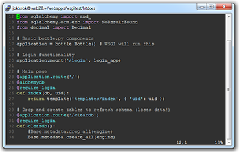
Well, Vim is great, but an additional bonus to its power is the fact that almost every *nix system has it preinstalled. So even if I’m not on my own computer, I can just launch an SSH client and use Vim to edit the piece of code I’m working on. No need to compromise. Except color schemes, which I just couldn’t get working over Putty. Today I solved that puzzle after one and half hours of googling, and thought to share the findings, maybe someone will find this the next time they face the problem.
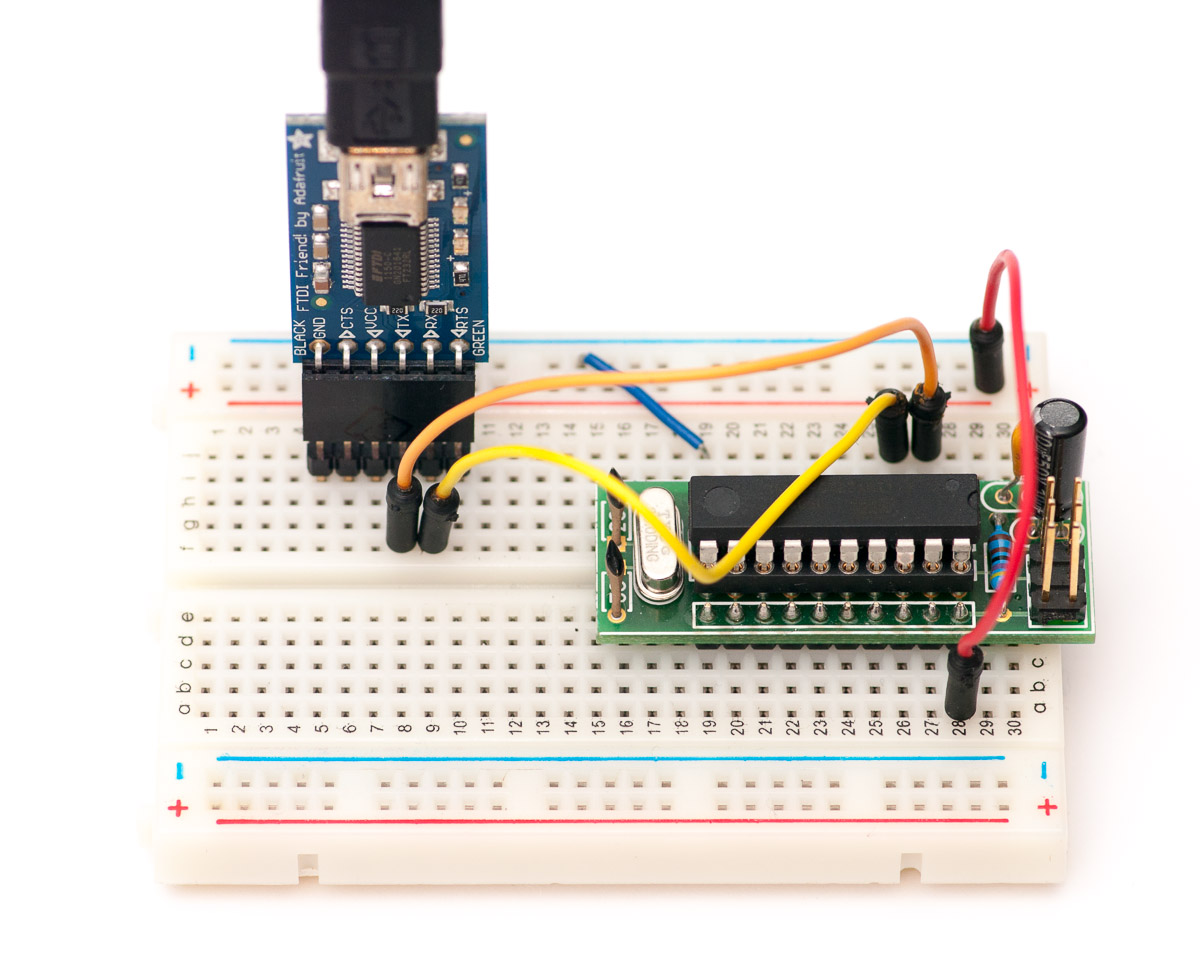
While banging my head against the wall with debugging my PS/2 keyboard thingy, I really wished I had a dedicated logic analyzer (preferably with PS/2 decoder, but even raw binary data would’ve been fine). So I decided to try out a long hatched idea – combine an ATtiny2313 and FTDI for some unlimited-length logic capturing with a PC. You’ll only need:
ATtiny2313
20 MHz crystal and caps (slower will also work, frequency just defines what baud rates you’ll achieve)
Optionally, some power-stabilizing capacitors, reset pullup and ISP programming header for flashing the firmware
ATtiny2313 is ideal for this, as it has all eight port B pins on one side in numerical order – attaching up to 8 logic lines is really straightforward. With 20 MHz crystal, baud rates close to 1 Mbps can be achieved in fast serial mode. I used Adafruit’s FTDI Friend for really simple (and way faster than most cheap serial adapter dongles) serial to USB conversion – just connect ATtiny RXD pin to TX, and TXD to RX, and you can even get power from the Friend so you’re all set! For crystal and that other stuff, see my ATtiny2313 breadboard header post for schematic, the picture above should fill you in with the rest.
Firmware code
This device has some of the smallest firmware codebases ever (firmware is 128 bytes). All we need to do is to set up UART with desired speed, and have the AVR chip to fire up an interrupt whenever data has been sent, and then use that to send current state of port B (using PINB):
#include <avr/io.h>#include <avr/interrupt.h>void USARTInit(unsigned int ubrr_value, uint8_t x2, uint8_t stopbits) { // Set baud rate UBRRL = ubrr_value & 255; UBRRH = ubrr_value >> 8; // Frame Format: asynchronous, 8 data bits, no parity, 1/2 stop bits UCSRC = _BV(UCSZ1) | _BV(UCSZ0); if(stopbits == 2) UCSRC |= _BV(USBS); if(x2) UCSRA = _BV(U2X); // 2x // USART Data Register Empty Interrupt Enable UCSRB = _BV(UDRIE); // Enable The receiver and transmitter UCSRB |= _BV(RXEN) | _BV(TXEN);}int main() { // 230.4 kbps, 8 data bits, no parity, 2 stop bits USARTInit(10, 1, 2); // replace 10 with 4 to get 0.5 Mbps sei(); // enable interrupts while(1) {} return 1;}ISR(USART_UDRE_vect) { UDR = PINB;}
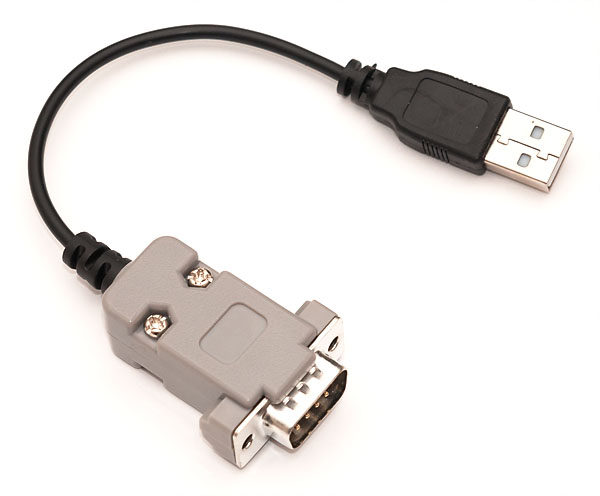
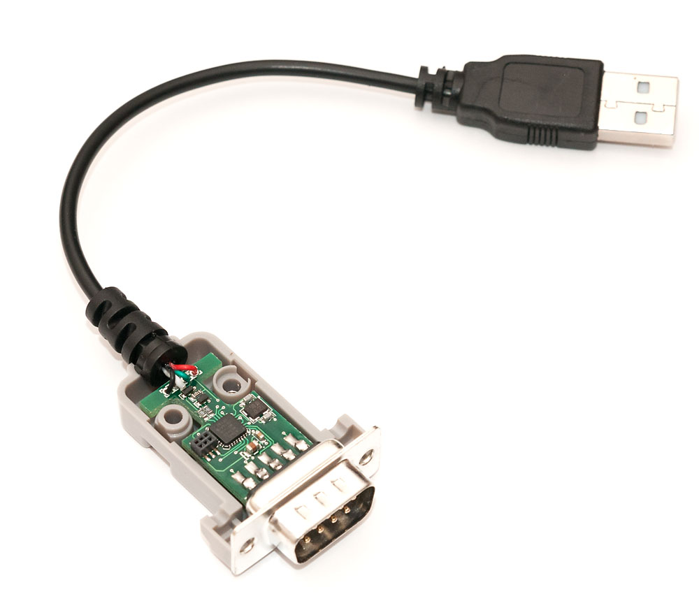
There are a ton of cool gadgets available in eBay, and even though I sometimes do impulse buys, I rarely mention those in my blog. However, this extremely cool piece of retro tech is something I just cannot pass by without a comment: Retronic Design USB joystick adapter. It is essentially a joystick adapter for the popular 9-pin D-SUB connector used in many of the 80s consoles, most notably Atari, Commodore 64 and Amiga. On the outside, it’s not much to be excited about – USB connector on the one end, and grey dongle that accepts a joystick on the other. However, things quickly change when you open up the enclosure (click on the image for a large view):
Inside the D-SUB end there is a very neat little piece of engineering, and many of my readers probably know how to program it — it isn’t anything other than a ATmega8A, a 8-bit AVR microcontroller that employs the same V-USB library I’ve covered in my tutorials to appear as a USB HID device on PC side.
All the components are on one side, and you have to admire the tiny ISP header the Retronic Design guys have fitted on the PCB. And wait, it doesn’t stop there. On the Retronic Design web site, they have full specifications for the device, and the download page includes both schematic, as well as full source code to the firmware.
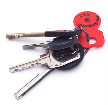
Something else than electronics this time: A real life hack for your keychain to make it possible for a finder to contact you in case you lose it, while maintaining full anonymity. There are commercial alternatives, but I already need the red plastic piece for shopping cart locks and decided two tags would waste valuable pocket estate.
Using my own phone number or e-mail was out of question, because they would easily lead to my home address. So I chose a very simple, free “public email” provider, Spambog. The service treats email addresses more like web URLs so there’s no expiration or need for password protection, but if you choose a too simple alias, chances are that someone else might choose to use it, too!
Spambog offers a nice RSS and URL options to follow the e-mail (no forwarding, though, but you should only receive 0-1 emails ever so who cares). And even if someone did choose the same alias, the only drawback would be the possibility of a random person receiving the same “I found your keys!” mail, and chances are they don’t live nearby and do robbing houses as side job.
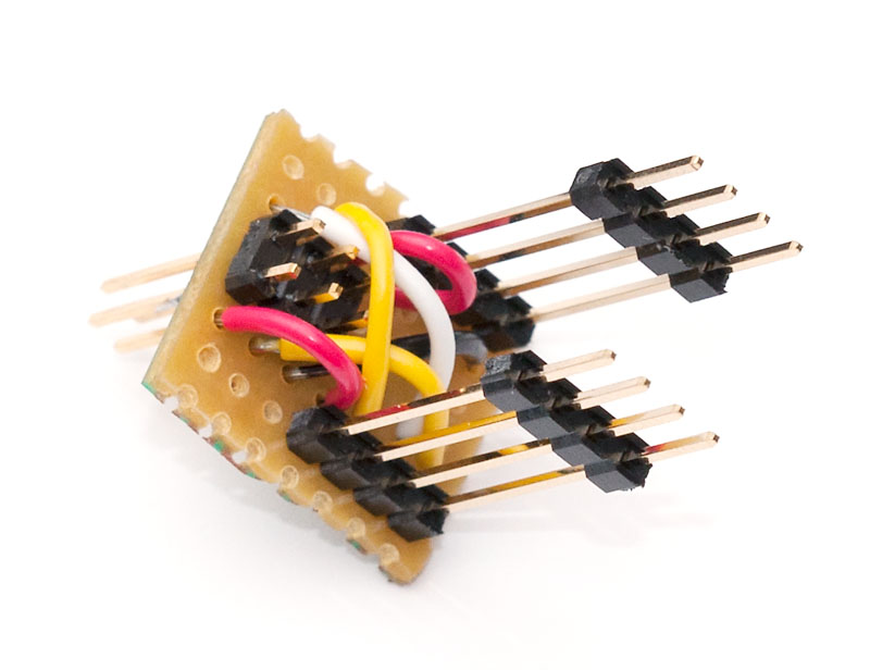
A quick weekend tip for a change, I thought to share a nice small soldering project will make programming ATtiny45 and ATtiny85-based projects a flash:
Basically I took a piece of veroboard, soldered some extra long pin headers on the bottom so it will form a tent of sorts above a ATtiny45/85 attached to a breadboard project. Then I soldered a 6-pin header to attach the ISP programming cable to, and used short pieces of jumper wire to route the header pins to correct ATtiny85 pins.
Now whenever I need to flash a ATtiny45/85 project sitting on a breadboard, I can just put this on top of that and never need to look up the pin layout again!
You can click the images for larger versions. I’ve also been quite busy with my PS/2 projects, so I have some nice material to share regarding that when I have some free time again in my hands!
Once I got my minimal AVR PS/2 keyboard device built, it quickly became apparent that such a device should be able to respond to rudimentary PS/2 commands if I would like to avoid irritating errors in BIOS and O/S side.
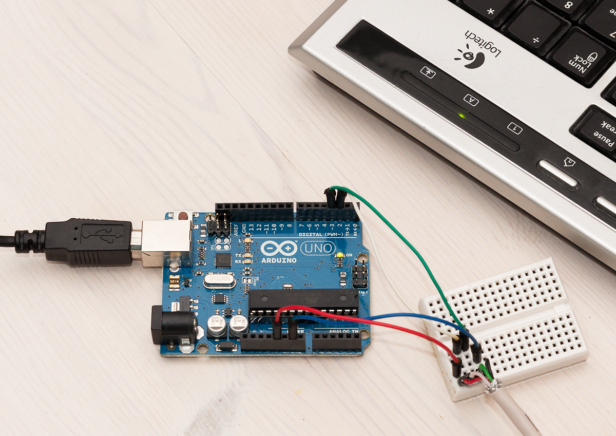
After spending a couple of educating evenings with my PicoScope (the only device I had at hand that could capture several seconds of PS/2 traffic at 100 kHz or more to make sure I detect each individual level change) and trying to understand bit-level PS/2 signals (I’ll maybe do a short post on that effort later), I decided it would be too complicated for debugging my own wanna-be PS/2 compliant device. So I decided to implement a simple PS/2 tester sketch with Arduino.
Basic Arduino Setup
There is already a great Arduino/Teensy library called PS2keyboard that had done most of the thinking work for me – the core of the library is an interrupt routine that is called automatically when the Arduino detects falling edge (logic level going from HIGH to LOW) on the clock pin. In Arduino Uno, pin 3 is attached to INT1, and setting up the interrupt is very simple:
#define CLOCK_PIN_INT 1 // Pin 3 attached to INT1 in Uno// ...attachInterrupt(CLOCK_PIN_INT, ps2int_read, FALLING);