I’ve been quite busy with work and had a few fully booked weekends, so no updates in a while. Well, it’s going to change now, as I have two more updates in the pipeline already! The first one is an interesting project that’ll surely interest those that have read my USB tutorials: Alvin Chang has started a USB password generator project at indiegogo!
Mr. Chang’s project is inspired my USB password generator hack, and builds upon the (GPL licensed) codebase it also used. Many people have expressed the desire to get the USB password generator as a ready-made device, so if you’re one of those, check out the project and decide yourself if you want to participate funding in the Aladdin key project:
Note: I’m associated with the project only via the DIY password generator hack that the project is partly based on (basic hardware design and source code).
After receiving my Stellaris Launchpad, I decided to browse the little amount of tutorials there was available on the subject. I was really impressed by the Getting Started hands-on workshop offered in TI’s wiki. After watching the first few tutorials, I had a somewhat firmer grasp on how this little puppy was supposed to be programmed, and the capabilities of the Code Composer Studio IDE.
I got as far as Chapter 4: Interrupts until I hit the first snag: After the Lab4 assignment, the friendly instructor told that as a home assignment, one could try out the PWM (pulse-width modulation) capabilities of the Launchpad before proceeding further. Little did I know how many hours I would spend on that topic! After a solid 8 hours of banging my head against the documentation, Launchpad and CCS (which is prone to hanging at least on my PC), I finally got it working, and decided this would be a great place for a tutorial.
Rule 1 of PWM on Launchpad: There are no PWM units
The initial four hours of my PWM efforts were spent on the StellarisWare Driverlib documentation concerning PWM. In case you haven’t yet watched the tutorials, the Driverlib is essentially a bundle of code that takes away the burden of writing into dozens of control registers, and instead presents the programmer with a couple of hundred API calls to enable a higher-level approach.
It wasn’t until the third hour of googling around that I discovered, that while the timer functionality of the Launchpad includes a PWM mode, there are no actual PWM units on board! So if you’re looking at the PWM functions in Chapter 21 of Stellaris Peripheral Driver Library User’s Guide – stop it and get back to the Chapter 27: Timer functions.
Step 1: Setting up the timer0 PWM mode
So the only PWM functionality the Launchpad supports is the “PWM mode” of the six hardware timers. Thankfully, that’s already quite nice (if I ever find out how to use interrupts with PWM, even better). So unless you already know how the timer system works, now’s a good time to watch the Chapter 4 video which explains it quite nicely. Based on that tutorial, we learn that the following piece of code should initialize the timer for us:
The most popular project of all time at Code and Life has been my DIY USB password generator. When I made it, I used a piece of veroboard that just fit inside a USB memory stick enclosure. Well, guess what: Benjamin Lunt just recently designed a custom PCB for it! I’ve been exchanging e-mails with him (Ben has written a book on USB, another very popular topic also in my blog) and he was kind enough to ship me one of these neat boards. Here’s what it looked like:
In addition to a nice USB connector footprint, this design also has a green power LED and a red transmission LED (which needs a small firmware change). Once assembled, the thing is really tiny, and it does work great. Thanks a lot for Mr. Lunt for designing this one! Be sure to visit his blog, as he’s interested if anyone would also like to have one (I know I did :). Maybe he’ll even publish the design files if someone wants to tinker with it (of course making your own isn’t too hard either).
On the right you can see what mine looked after some soldering (click for a larger image) – I love the fact that small resistors from Partco all had different base color for different values… I had to compromise a bit and use 48 ohm resistors instead of 58, and 4k7 instead of 2k2. For the LEDs, I used 480 ohms.
My local electronics store Partco overdid themselves again. Believe it or not, while most of the people in US are still waiting their Stellaris Launchpads, this small Finnish electronics outlet had several in stock. Thanks to two generous donators of $11 and $1.5 respectively, I also had the financial leverage to acquire one. :)
The board came in a decent black cardboard box with a small quickstart booklet – see Hack-a-Day hands on coverage for details on the package. Even the board itself contains the URL where you can get the software package. I proceeded to download the 1.3 GB Code Composer Studio + StellarisWare package. It took 30 minutes to download, thanks to less-than-impressive transfer speeds from TI, and another 1 hour to install.
The guys at TI were generous enough to include working quickstart / driver installation guide with the package, and for once, I was actually able to walk through it without any “oh this doesn’t work anymore” -moments. Even the three drivers required were found under Software/ICDI in the setup package. Kudos! As a result of installing CCS and StellarisWare, I now had 3.75 GB and 63 872 files of additional hacking capability on my hard drive. Gone are the days where you could fit an IDE into four floppies like my Borland Turbo C++ 3.0!
Taking it for a test drive
I first followed TI’s quickstart tutorial to the end to get some blinky LED action, and even tried out the UART example – even that worked out of the box with Putty set to COM25 and 115 200 baud rate. Next I made my own project by shamelessly following the recent HaD Getting Started guide.
Sure enough, the LEDs were now blinking just like I wanted them to – and blinding me in the process: whoever thought that you need SMD LEDs that are bright enough to leave light trails on my retina must’ve been utterly mad. I recommend either wearing sunglasses (might not be enough – seriously) or placing something near-opaque (like a piece of white paper) between yourself and the Launchpad when working with the LEDs for any longer periods.
However, I couldn’t yet find much information about input side, so after some searching, I located the documentaion for StellarisWare peripheral drivel library, SW-DRL-UG-9453.pdf and started reading. Armed with that and the short “Stellaris LM4F120 LaunchPad Evaluation Board User Manual” that was found from Documentation/Board/EK-LM4F120-UM.pdf I quickly wrapped up something that was supposed to turn red and green LEDs ON when pressing user switches SW1 and SW2, respectively:
After a few busy weeks, I’ve finally arranged enough time to cover the details behind my color composite video decoding project I featured recently. Before you proceed, I suggest you read the previous post, as well as the one before that covers B/W decoding (this post builds on that one), and watch the video, if you haven’t already:
So, feel ready to learn about composite color coding, quadrature amplitude modulation (QAM)? Let’s get started! Before you get going, you can grab the example excel file so you can view the diagrams below in full size, and study the data and formulas yourself.
Combining luminance and color information
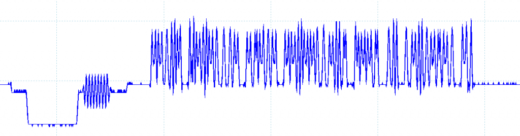
If we look at one line of video information (“scanline”), it’s basically a function of two things: luminance (brightness) and chrominance (color) information, combined to a single waveform/signal like this one I showed in my first article.
If we’d like to just have a black-and-white image, encoding it would be easy: Maximum voltage for white, minimum voltage for black, and the values between would simply be shades of grey. However, if we’d like to add color information to this signal, we need to get clever. What the engineers in the 1960’s did to get two things stuffed into one signal was to add color in sine wave modulated form on top of the luminance signal. With proper analog electronics, these two signals could then be separated from the receiving end.
I’ve been quite busy the last two weekends, first on a weekend holiday trip to Tallinn, Estonia, and then playing in the Helsinki Casual go tournament which successfully took most of my time last weekend. This has somewhat delayed my continuation to the composite video decoder project.
However, I haven’t been resting on my laurels completely even electronics-wise. My trip to Tallinn had one good by-product, namely new Audiotechnica ATH-M50 headphones. They are a marked improvement over my previous HD-500 Sennheisers, and got me inspired to getting a headphone amp, a tube-based Little Dot mkIII to be more exact. The 32 ohm ATHs don’t necessarily need an amp, but now I’ll at least be prepared if I ever end up getting something like HD-650s.
While researching for a proper USB DAC I came across an amazingaudio blog by NwAvGuy. Compared to a lot of “audiophile” coverage he seems to have a solid engineering perspective to audio issues, and he has put an amazing effort to long articles that deal with many issues that surround headphone amp gear.
In addition to great scientific info, NwAvGuy has also designed a USB DAC called ODAC, which I ordered from Head’n’Hifi (they conveniently ship inside EU so no customs). And while I was at it, I couldn’t resist getting a DIY version of NwAvGuy’s O2 headphone amplifier. Read on for my experiences on building it and pitting it against the Little Dot mkIII tube amp.


