I have spent a fair amount of time with 8-bit AVR microcontrollers and one of the cooler things has been the V-USB library which implements low-speed USB with clever (and very time-critical) bit-banging. The popularity of my USB tutorials is a testament to its usefulness, and I’ve gotten lots of mileage out of that.
There are, however, some limitations to software USB with such a low spec microcontroller. USB communication hogs up the MCU completely during USB communication, which means you lose dozens of microseconds in random (or in many cases 8 ms) intervals. This rules out things like software UART at reasonable speeds (which I discovered when trying to implement MIDI on Adafruit Trinket). And more powerful ATmega328-based dev boards like Pro Trinket start to get quite large.
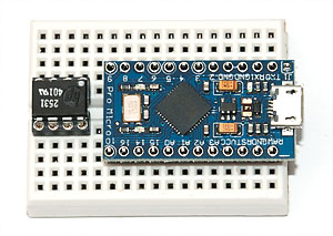
Not so with this tiny beauty shown in the image. It’s a ATmega32U4 based board, where the U4 means it has hardware USB support. The form factor is extremely compact 12 pin header length, which leaves 5 rows free on the smallest prototyping breadboards. That means you can have a DIP8 component with a few resistors on the same breadboard (such as a 6N137 optocoupler which is nice for MIDI… ;).
And the best part is, that because the chip is flashed with same firmware used in Arduino Leonardo (and a largely matching pinout), you can use Arduino for programming, and avrdude supports it out of the box.
Actually, scratch the above statement. The best part is the price. The board is based on Sparkfun Pro Micro 16 MHz, but it’s actually a Chinese clone, which you can get for $4 via DealExtreme and from quite many places in AliExpress: Just search for ATmega32U4 and they will come up. This means you can just order five and solder them into whatever project you’ll make permanently. And unlike Arduino Micro (for which clones exist as well), this has the micro-USB port already in place.
Using Pro Micro without Arduino IDE
Now you can just follow SparkFun’s instructions on how to use that thing on Arduino (short version: select Leonardo as board type, and look up the schematic if you are unsure which pins are connected to LEDs, etc.). But if you’re like me and want to get to raw metal, avr-gcc and avrdude is the way to go. Here’s a simple blinky demo:
Among my recent electronics purchase spree was the amazing Teensy LC from PJRC. It has a nice ARM Cortex-M0+ processor, real hardware USB, and what’s the nicest part, an Arduino add-on called Teensyduino which enables easy programming with Arduino, but with support for many of the hardware features.
Now I started playing piano a while ago, and just a few weeks ago bought a Pianoteq license to send notes via MIDI to my computer, and render high quality piano sound to speakers. However, it turns out my $8 USB-MIDI adapter from DealExtreme had a less than perfect implementation, essentially changing pedal events into “note on” events!
Thankfully, I had a MIDI connector and a high-speed optocoupler at hand, and with these I could implement a MIDI in rather easily. After some investigation with Arduino Uno, it seemed quite simple to receive the serial MIDI bytes and dump them over Arduino serial (I’ll write another post about this later).
However, Arduino cannot become a USB MIDI device very easily, so here comes the really nice part: Teensy LC can, and the Teensyduino add-on included a working USB MIDI and also serial MIDI libraries!
The Hardware
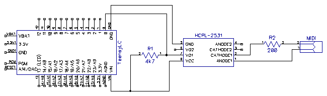
The Wikipedia page for MIDI essentially shows the required circuitry for receiving MIDI data – wire the DIN cable pins 4 and 5 through the receiving side of optocoupler and put a 200 ohm resistor in series with it. A diode is also suggested for reverse current (ESD) protection, but I skipped that. You can start with a LED instead of optocoupler to see it lights up if you’re unsure you have pins 4 and 5 the right way. Or just put the LED (with a resistor) on the other side of the optocoupler first.
The HCPL-2531 I had at hand requires an additional VCC connection on the sending side. After some experimentation, a 4k7 ohm pullup resistor between VCC and VO1 (NPN-transistor base?) gave the cleanest signal out. The wiring diagram (thanks Diptrace!) is shown below:
Happy New Year 2016! After a long hiatus in electronics, I have been quite busy in the last month or so. I have a bigger (USB MIDI related) project posting coming up, but just wanted share a small nugget already.
I ordered a big chunk of things recently from Adafruit shop and Sparkfun. Among them was the lovely Adafruit Trinket (which actually came as a free bonus because I spent way too much on black friday :).
Now I am planning a project which involves transforming the very compact, but already USB-enabled Trinket into a USB MIDI device. However, there are two problems:
Adafruit examples for USB come in Arduino form
There are no USB MIDI examples
I somewhat dislike the high-level Arduino environment in cases where low-level performance is needed (and the V-USB implementation is one of those places), and for my later MIDI part, I will need fine-grained control to juggle serial communication and USB. Also, all USB MIDI examples are on “bare metal”, so the Adafruit example Arduino code would require deeper knowledge of Arduino inner workings than I have.
Time to do some chopping!
Slimming Down the TrinketKeyboard Example
I decided to adapt the excellent base code in Adafruit Trinket USB GitHub repository, but trim the keyboard example to bare essentials (my next step will be to transform it into a USB MIDI device, so the less code I have to adapt, the better). Turns out this was quite simple to do:
It’s been ten months since I got and reviewed the Topre Realforce 88UB. I’ve been very satisfied with the keyboard, the only real issue being that for some reason my brain is having strange difficulties with adjusting to the new microlayout since my time with HHKB — for some reason I still hit adjacent keys quite a lot when coding, getting # instead of % or ‘k’ instead of ‘j’ (doubly frustrating with Vim!).
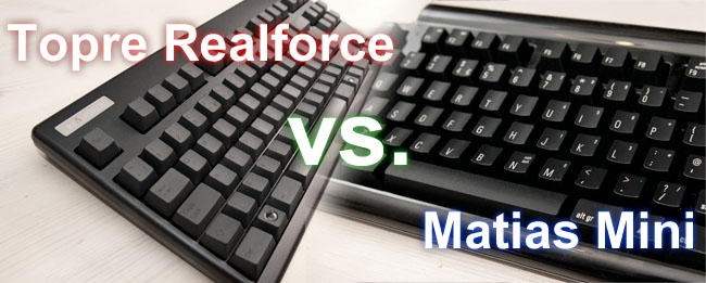
However, the thirst for new experiences never really leaves you, so I decided to try out the Matias switches that have caused quite a lot of discussion at Geekhack. Since I’ve liked the low thud of Topre keys and loved the compact layout of RF 88UB, I decided I’d see how the Matias Mini Quiet Pro compares to my Realforce.
After using the Matias keyboard extensively for several weeks, I think I have enough experience to write a bit about this new entrant to the rather established Cherry/Topre/Unicomp triopoly of mechanical niche keyboards. To make it more interesting, it’ll be a shootout against the reigning king, Topre Realforce 88UB. Fight is on!
Warm-up Round: Specifications and Price
I got my Realforce through The Keyboard Company in UK, and they were kind enough to provide the Matias Mini review unit for this shootout. As a thanks I’m including their banner here, and based on several years of personal experience I can really recommend them, especially if you’re within EU as there will be no customs fees.
Specification-wise the Realforce and Matias are quite similar with reduced tenkeyless layout sporting function and cursor keys. The Topre has standard pageup/pagedown etc. column whereas Matias a bit more compact but requires a function key to access insert, home and end and the more esoteric print screen, scroll lock and pause/break keys. Price-wise, the Matias sits in the not-quite-inexpensive $160 price range, but the Topre almost doubles this with its hefty $295 price tag.
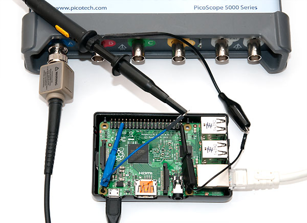
It’s battle time! Some of you may have heard that Raspberry Pi 2 is out with more punch than ever. Just how much more? Well, apt-get dist-upgrade went about 5 times faster with the new Pi. With 1 GB of RAM and four cores, this will definitely be a boost for my home SSH box ergonomics over the previous version.
But what about hacking? There has been a lot of interest in getting GPIO benchmarks for the Pi 2 similar to my earlier Raspberry Pi GPIO benchmark. Well here it is! Please refer to the earlier article for source code and nice screenshots of square waves, as I’ll concentrate on the performance difference only here. You can also get the code from Github:
All the Pi 1 benchmarks were ran 14th and 15th February 2015 using latest versions of the libraries as stated in my updated benchmark post. Pi 2 benchmarks were all run 25th and 26th March 2015 with the latest versions. If you get significantly different results at a later date, please let me know and I’ll update the table!
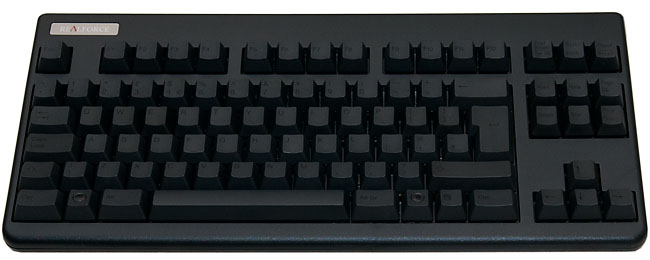
This is my review of the Topre Realforce 88UB mechanical keyboard with evenly weighted 45g switches and UK layout. This is the ISO layout sister model of the Topre Realforce 87U (87UB / 87UW) so everything in this review will apply for that model, except a few layout details regarding the extra keys. Before diving into details, a short background of my previous journey:
Two years ago I got really interested in high quality mechanical keyboards. After all, the keyboard is the instrument I use several hours every day, so if I am spending close to 2000€ on a workstation and display, why should I compromise with a cheap 30€ keyboard, especially since the keyboard will likely last several workstation lifespans?
After heavy research I settled on Happy Hacking Keyboard 2 Professional due to its compact “hacker” layout which seemed great for vim, and Topre key switches, which many consider to have the very best tactile feel. See my review of the HHKB2 keyboard for details.
However, in two years of typing with the HHKB, I never fully learned to use function key bindings for cursor keys and Home/End fluently. Coding with Vim somewhat alleviated the problem, but every time with a command prompt or a shell this nagged me. Also, playing games required a separate keyboard, as most games make use of function keys, and many make use of both WASD and cursor keys. It was time for something else. Something better.
Topre Realforce 88UB – Best of both worlds?
After my experience with HHKB, I had the critical components for my dream keyboard well thought out:
Tenkeyless model with dedicated cursor and function keys. I’ve also used CM Quickfire TK and I can say from experience it is a terrible idea.
ISO layout, so I get the \ and | right next to my right pinky, and an additional key next to z to get < and > in Finnish keyboard layout (it doubles as another \| in US layout)
Topre switches for the ultimate typing comfort. Having used rubber dome, scissor mechanisms and Cherry MX blues, and trying out reds, blacks and browns, there really is no competitor. Buckling spring is just too heavy and noisy for my taste.
The items 1 and 2 are quite easy, but the third one essentially meant that the Topre Realforce line would be the primary candidate to fill all these needs. I’ve used The Keyboard Company before and they have a superb selection of Topre models, so I quickly zoomed in on the black 88-key model with UK layout: