Recording 433 MHz Radio signals with Seeed XIAO RP2040
Having done 433 Mhz radio signal recording with PicoScope 2208B MSO and Raspberry Pi 4, Arduino Uno and regular USB soundcard, I figured, why not add one more to the mix: Let's try the RP2040!
Compared to Arduino Uno, the RP2040 has major advantages for this project:
- Much higher clock frequency of 133 MHz means there's cycles to spare even at ~1 Mhz rates
- Relatively vast SRAM memory, 264 kB vs. 2 kB
- Native C SDK that is rather easy to work with
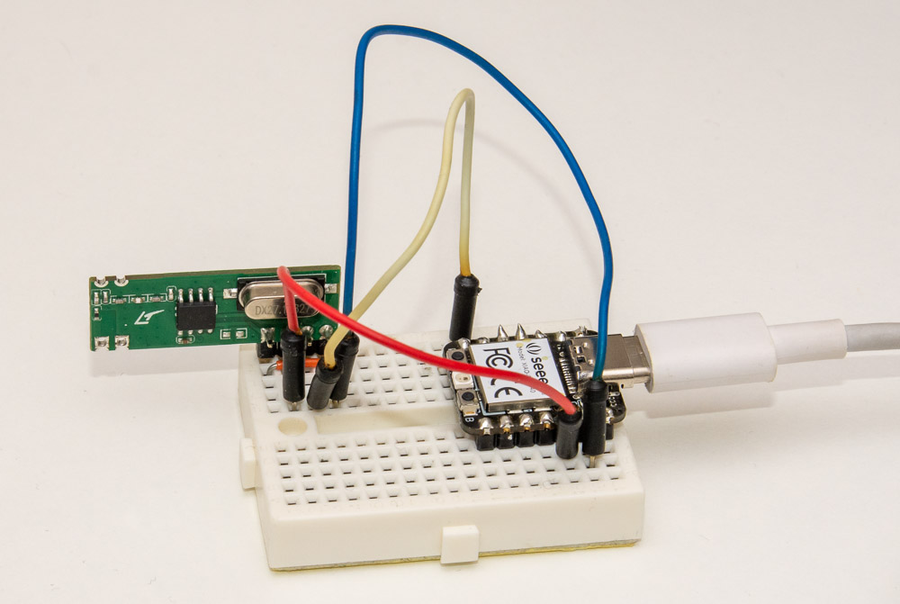
I'm using the Seeed XIAO RP2040 for this project. It is extremely compact and has a nice USB-C interface. You can see the wiring, it's just 3.3V and GND to the receiver (which luckily did work fine with that voltage) and signal to GPIO pin 0.
Note that while RP2040 pinout has 5V supply line, the GPIO pins are not 5V tolerant, so you should not power a 5V receiver and directly connect it to pin 0. A voltage divider is strongly recommended to avoid longer term damage to the RP2040 pin.
Setting up RP2040 programming environment
I basically followed the Getting started guide that was linked from the Pico SDK Github to get the Blink example working. After that, it was quite simple to set up a new project following the "Quick-start your own project", setting up CMakeLists.txt like this:
cmake_minimum_required(VERSION 3.13)

# initialize the SDK based on PICO_SDK_PATH
# note: this must happen before project()
include(pico_sdk_import.cmake)

project(joonas-pico)

# initialize the Raspberry Pi Pico SDK
pico_sdk_init()

# rest of your project
add_subdirectory(logic_analyze)
In the logic_analyze subfolder I copied the Interrupt triggered GPIO example to continue from. You can grab the full example as a zip here and run pretty similar set of commands as in the SDK guide:
$ mkdir logic_analyze
$ cd logic_analyze
$ wget https://codeandlife.com/images/2023/logic-analyze-pico.zip
$ unzip logic_analyze-pico.zip
$ mkdir build
$ cd build
$ export PICO_SDK_PATH=../../pico-sdk
$ cmake ..
$ make
Note that this assumes you placed the example directory logic_analyze alongside your pico-sdk directory.
After running make, you should find the logic.uf2 file under logic_analyze directory and you can just drag and drop it to your RP2040 when it is in USB drive mode.
C Code for Recording GPIO Changes
The code is basically combination of what I did for Arduino and Raspberry Pi, and the hello_gpio_irq and hello_timer examples. Basic logic:
- Setup
stdio_init_all()(over USB, necessary definitions to enable that inCMakeLists.txtfile) and wait untilstdio_usb_connected()returns true. - Loop forever, asking the user over serial (USB) to press a key to start recording
- Clear receive buffer
- Set alarm timeout of 5 seconds to end recording if buffer hasn't been filled
- Set up GPIO interrupt triggers on rising and falling edges of pin 0
- In the interrupt handler, record time elapsed since last edge using
time_us_64() - Once timeout is reached or buffer has been filled, disable GPIO interrupt and print out received timings.
Here's the main method:
int main() {
    stdio_init_all();
    while(!stdio_usb_connected());

    while(true) {
        printf("Press any key to start.\n");
        getchar_timeout_us(100*1000000);
        printf("Started!\n");

        for(int i = 0; i < BUFSIZE; i++) buf[i] = 0; // Clear
        pos = 0;
        timer_fired = false;

        add_alarm_in_ms(5000, alarm_callback, NULL, false);

        gpio_set_irq_enabled_with_callback(0,
                                           GPIO_IRQ_EDGE_RISE | GPIO_IRQ_EDGE_FALL,
                                           true, &gpio_callback);

        while(!timer_fired && pos <= BUFSIZE) tight_loop_contents();

        gpio_set_irq_enabled(0, GPIO_IRQ_EDGE_RISE | GPIO_IRQ_EDGE_FALL, false);
        printf("Ended.\n");

        for(int i = 0; i < pos; i++) printEdge(buf[i], i&1);
    }
}
Alarm and interrupt callbacks are rather straightforward:
volatile bool timer_fired = false;

int64_t alarm_callback(alarm_id_t id, void *user_data) {
    timer_fired = true;
    return 0; // could return a value in us to fire in the future
}

volatile uint64_t prev = 0;

#define BUFSIZE (1024)
uint16_t buf[BUFSIZE];
volatile uint32_t pos = 0;

void gpio_callback(uint gpio, uint32_t events) {
    uint64_t now = time_us_64();
    uint16_t d = now - prev;
    bool high = events & GPIO_IRQ_EDGE_FALL;
    prev = now;

    if(high && !(pos & 1)) pos++; // put HIGH timings at odd positions
    if(pos < BUFSIZE) // avoid overflow
      buf[pos++] = d;
}
Note the if(high && !(pos & 1)) that advances the position where (previous) high edge duration is stored, ensuring that low edges are in even indices, and high edges at odd ones.
I adapted a simplified version of the "timings to letters" conversion from my previous post for this one. You could just print out the raw timings as well if you don't know what times your are expecting:
uint16_t times[2][6] = {
    {0, 250, 1250, 2500, 5000, 0xFFFF},
    {0, 250, 500, 0xFFFF}
};
char letters[2][6] = { "#._L\n", "$-\n"};

void printEdge(uint16_t d, bool high) {
    // Pick times and letters based on high parameter
    uint16_t *t = times[high?1:0];
    char *l = letters[high?1:0];

    // Find nearest time in t to d until we reach 0xFFFF
    int bestC = l[0], bestD = abs(d-t[0]);
    for(int i = 1; t[i] != 0xFFFF; i++) {
        if(abs(d-t[i]) < bestD) {
            bestC = l[i];
            bestD = abs(d-t[i]);
        }
    }
    putchar(bestC);
}
The code basically goes through either the first or second index of times and letters based on logic level, and prints out the letter that is closest to given timing, breaking the evaluation when 0xFFFF is reached. I chose carriage return as the final non-terminating timing so my Nexa codes streams are nicely separated by newlines.
If you didn't read through previous parts of this series, it's enough to know that Nexa repeats a signal consisting of 250 us high pulses separated by 250, 1250 or 2500 us low pulses, with 10 ms (10 000 us) delay between the five (or more) repeats in low (not transmitting) state.
Trying it out
After flashing the project, I used Device Manager to discover the COM port taken by the device (it was COM15), and connected to it with Putty (serial rate for USB is 9600 baud I recall, might not matter with the CDC device). Here's how it looks like when I press a button on my Nexa remote:
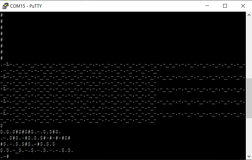
The "high, long (L) pause and morse" sequences are pretty easily decipherable from here already. Copy-pasting to Notepad gives it in text form:
.-L-.-_-.-_-.-_-_-.-_-.-_-.-_-.-.-_-.-_-.-_-.-_-.-_-.-_-_-.-.-_-.-_-.-_-.-_-.-_-.-_-.-_-_-.-.-_-_-.-_-.-.-_-.-_-_-.-.-_-.-_-.-_-.-_-
-L-.-_-.-_-.-_-_-.-_-.-_-.-_-.-.-_-.-_-.-_-.-_-.-_-.-_-_-.-.-_-.-_-.-_-.-_-.-_-.-_-.-_-_-.-.-_-_-.-_-.-.-_-.-_-_-.-.-_-.-_-.-_-.-_-
-L-.-_-.-_-.-_-_-.-_-.-_-.-_-.-.-_-.-_-.-_-.-_-.-_-.-_-_-.-.-_-.-_-.-_-.-_-.-_-.-_-.-_-_-.-.-_-_-.-_-.-.-_-.-_-_-.-.-_-.-_-.-_-.-_-
-L-.-_-.-_-.-_-_-.-_-.-_-.-_-.-.-_-.-_-.-_-.-_-.-_-.-_-_-.-.-_-.-_-.-_-.-_-.-_-.-_-.-_-_-.-.-_-_-.-_-.-.-_-.-_-_-.-.-_-.-_-.-_-.-_-
-L-.-_-.-_-.-_-_-.-_-.-_-.-_-.-.-_-.-_-.-_-.-_-.-_-.-_-_-.-.-_-.-_-.-_-.-_-.-_-.-_-.-_-_-.-.-_-_-.-_-.-.-_-.-_-_-.-.-_-.-_-.-_-.-_-
Now the short pulses look like -.- with longer underscores between them. We can make this simpler to read by replacing "three prong" signals (-.-.-) with 3, -.- with 2 and finally - with 1:
.1L2_2_2_1_2_2_2_3_2_2_2_2_2_1_3_2_2_2_2_2_2_1_3_1_2_3_2_1_3_2_2_2_1
1L2_2_2_1_2_2_2_3_2_2_2_2_2_1_3_2_2_2_2_2_2_1_3_1_2_3_2_1_3_2_2_2_1
1L2_2_2_1_2_2_2_3_2_2_2_2_2_1_3_2_2_2_2_2_2_1_3_1_2_3_2_1_3_2_2_2_1
1L2_2_2_1_2_2_2_3_2_2_2_2_2_1_3_2_2_2_2_2_2_1_3_1_2_3_2_1_3_2_2_2_1
1L2_2_2_1_2_2_2_3_2_2_2_2_2_1_3_2_2_2_2_2_2_1_3_1_2_3_2_1_3_2_2_2_1
Noting that the signal starts with a brief "low" and then repeats five times with longer pause (L) in the beginning and shorter pauses between the numbers, we could just write the one repeat like this:
1 222122232222213222222131232132221I recorded all the 5 on&off buttons of the Nexa remote and you can see a pattern emerge:
| Button # | on/off | common prefix | on/off | button |
|---|---|---|---|---|
| One | on | 1 22212223222221322222213123 | 2132 | 221 |
| One | off | 1 22212223222221322222213123 | 2222 | 221 |
| Two | on | 1 22212223222221322222213123 | 2132 | 212 |
| Two | off | 1 22212223222221322222213123 | 2222 | 212 |
| Three | on | 1 22212223222221322222213123 | 2132 | 131 |
| Three | off | 1 22212223222221322222213123 | 2222 | 131 |
| Four | on | 1 22212223222221322222213123 | 2132 | 122 |
| Four | off | 1 22212223222221322222213123 | 2222 | 122 |
| "G" | on | 1 22212223222221322222213123 | 1232 | 221 |
| "G" | off | 1 22212223222221322222213123 | 1322 | 221 |
Conclusion
Pretty nice! Just 78 lines of code and we were able to create quite a simple 433 MHz signal receiver that prints out the Nexa remote signals. Compared to Arduino, buffer size could easily be made large enough to fit the signal received, and actually using edge trigger and microsecond precision timer lets us be pretty confident about the timings.
Testing out the code, I noticed that occasionally the signal broke, probably due to interference in the receiver. So it's nice to have the redundancy of the Nexa repeats to get it right.