One exciting piece of hardware I received with my Digikey order was an Arduino Uno board (R3). There was conflicting information whether or not it could be used as an ISP (in-system programmer), so I decided to see for myself. It turned out that with just one tweak, I could use the $26 device to program my AVR chips, essentially eliminating the need for a separate ISP such as $22 USBtiny!
This is obviously good news for any beginner with a budget, so I decided to write a short tutorial on how to do it. I used my USB password generator as a guinea pig for this project, so if you have wanted to try that out, this post also doubles as tutorial on how to build it on breadboard (good idea in any case before soldering it anywhere). Read on for details!
Minimal circuit for AVR-powered USB
For this exact project, you’ll need the following components (of course you can also build something else, as long as the Arduino can power it):
ATtiny45/85 (the 20PU version, not the low-voltage one)
Until now, I’ve been ordering all my electronics supplies through the excellent Finnish firm Partco. However, after running out of ATtiny85 chips I just couldn’t make myself pay 5.90€ ($7.80) when the same part was available for third the price from Digi-Key. I decided to try the fabled distributor myself. In case you haven’t tried them yet, read on for my experiences.
Website and Shopping Process
It is surprising how such a successful electronics component retailer is able to operate with such a poorly laid out and difficult to use website. From a usability standpoint, it’s a prime example of how not do design a web store. There’s so much to critize it’s hard to know where to begin, but here my top annoyances for the front page alone:
Most prominent items are the site ad and a rotating banner. First will become redundant after initial visit (possibly even before), and with 600 000 products stocked, the second banner has a very low probability of being of interest
Most of the 11 choices in navigation pane are for functionality that is not relevant for most visits – product index and order handling would likely cover 98 % of user needs
No color coding or any other visual aid is used to group menu items in general categories (I’d categorize them as “Ordering”, “Products”, “Information and Resources” and “Help”)
Product hierarchy is not built into navigation in any way – you essentially have to start all over again if you find out that the sub-category you chose wasn’t the correct one
The “interactive catalog” that I mistakenly first went into (instead of “product index”) is essentially a e-paper version of 3000 page catalog. A link to such monster should be buried deep instead of frustrating first-time (and possibly last-time) visitors
Overall, no visual sections other than “red boxes” exist in the user interface, making it hard to group different types of information
I’m planning to make some RFID hacking in near future using 150 kHz tags. Since I don’t have a signal generator, I decided to go where quite many people have gone before and build myself one, more specifically a DDS. Instead of just taking a complete project from the net, I thought this would be a good way to learn a bit of AVR assembly programming, and manual D/A (digital to analog) conversion using R-2R ladders. Here’s what I built:
I’m skipping the schematic to save some time – basically it’s a ATmega88 with 6-pin programming header, power, a 16 MHz crystal (other frequencies also work, lfuse for this setup if 0xFF) and a red LED that is not used. The R-2R ladder is wired with white jumper wires to PB0-PB5 (it’s a 6-bit DAC) so that PB0 is the “least significant bit” and PB5 the most significant one. Read on for details.
R-2R ladder in brief
The analog to digital converter in this project is a R-2R ladder built from 10 kOhm (R) and 20 kOhm (2R) resistors. By providing GND/VCC to the points a_{0}..a_{n-1} (see the diagram below), a voltage between GND and VCC * (1-1/2^n) can be seen at V_out (in this example n=6 and V_out can reach 63/64 of VCC).
If you want to check that it actually works, you can start with 1-bit version and easily see that when a_0 is 0V/5V, V_out is 0V/2.5V (5*(1-1/2^1)). If you derive a Thevenin equivalent circuit for this, you get one with 0/2.5V voltage source and 2R resistor in series. By adding another bit to this equivalent circuit, you can verify that the 2-bit version works also and it’s Thevenin equivalent resistance is also 2R – and by induction, you see that after any number of bits, the resistance stays at 2R and voltage is:
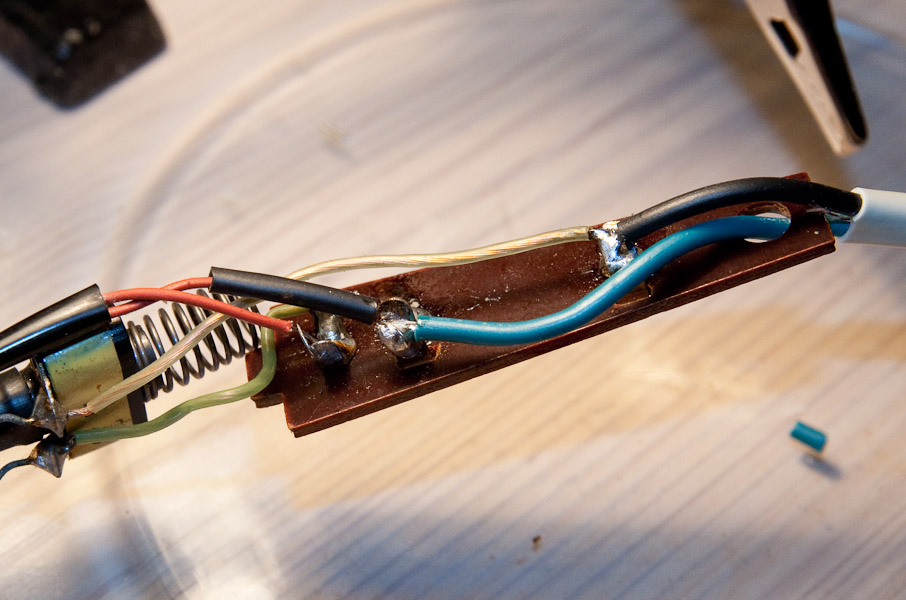
Immediately after soldering together my USB password thingy, my solder iron, the family heirloom Weller Magnastat stopped working. Some investigation showed that the base station was providing 24V AC voltage just fine, so I decided to unassemble the handpiece to see if something could be done. Here’s what I found:
It turned out my iron was salvageable; read on to learn a bit about the Magnastat and how I was able to repair mine.
Magnastat basics
The construction of the device is surprisingly simple (see this image): The first (blue) wire from A/C power unit goes straight to the heating element (first red wire with black tube around it). The second (black) A/C wire goes through the magnastat switch (brown and green wires) and then to the second heating element wire (second red wire without the black tube). A capacitor is wired parallel to the switch. With limited A/C experience I’m not sure if it’s for blocking DC current, smoothing the switch action or letting a small amount of A/C current through.
A long tube goes “out” the handle part into the iron tip, and the tip is placed at the head. The hollow tube above the tip is then placed over the tip and screwed to the base of the main assembly to keep the tip snugly in place. Here’s a diagram of the inner workings, from Cooper Industries’ website:
If you read a bit about the Magnastat, it turns out the temperature-controlling part, the “magnastat”, behind the tip is magnetic below a given temperature, and loses its magnetic properties above that: Initially the magnastat pulls the switch closed via a mechanism inside the long tube, but once desired temperature is reached, the magnetic property is lost and the switch opens. Once the tip cools down a bit, switch is pulled closed again, and so the temperature stays regulated.
Note that in my model the tip and the magnastat are one solid piece (magnastat is in the base of the tip), newer models have a separate magnastat and tip, and you can change the target temperature just by changing the magnastat part.
Having done half a dozen V-USB tutorials I decided it’s time to whip up something cool. As USB keyboards were an area untouched, I decided to make a small USB HID keyboard device that types a password stored in EEPROM every time it’s attached. A new password can be generated just by tabbing CAPS LOCK a few times (4 times to start password regeneration and one tab for each password character generated, 10 is the default password length). Below you can see the device in action:
The place I work at requires me to change my password every few months so this would be one way to skip remembering a new password altogether (as long as I remember to write it down before regenerating a new one so password can be changed :).
What is inside?
The device is powered with a simplified version of the hardware I used in my ATtiny85 USB tutorial – I stripped away the LCD, reset pullup and both capacitors. If you’re better in cramming components inside enclosures I suggest adding at least a 0.1 uF capacitor between VCC and GND, but it seems to work fine even without it:
If you’ve done even a bit of electronics, the chances are that you’ve already amassed a hefty collection of resistors. Buying them is fun but finding the right values from a stack of resistors is not. I noticed that you can buy actual “resistor folders” with nice labels and the full E24 series of 1500 resistors for $100. I already had resistors so I decided to make my own folder with less expense.
I walked into the nearest book store and quickly found a promising offering: 10 transparent plastic sheets of “collectible card holders” for about 3€. Any store having binders and associated supplies will probably have something similar. I also bought a thin A4 binder and 200+ label stickers for about 9.90€ total (about 1:1 to dollar prices). Here’s what I came home with (already added the stickers):
Each sheet had 9 pockets so for 3€ I get storage for 90 values, and 10-20 resistors fit into a pocket without making the page too heavy. I labeled the first 72 based on my E12 series and that left me with 2 extra pages for “exotic” resistor values. Here’s the first page of E12:


