Arduino PS/2 Keyboard Tester
Once I got my minimal AVR PS/2 keyboard device built, it quickly became apparent that such a device should be able to respond to rudimentary PS/2 commands if I would like to avoid irritating errors in BIOS and O/S side.
After spending a couple of educating evenings with my PicoScope (the only device I had at hand that could capture several seconds of PS/2 traffic at 100 kHz or more to make sure I detect each individual level change) and trying to understand bit-level PS/2 signals (I’ll maybe do a short post on that effort later), I decided it would be too complicated for debugging my own wanna-be PS/2 compliant device. So I decided to implement a simple PS/2 tester sketch with Arduino.
Basic Arduino Setup
There is already a great Arduino/Teensy library called PS2keyboard that had done most of the thinking work for me – the core of the library is an interrupt routine that is called automatically when the Arduino detects falling edge (logic level going from HIGH to LOW) on the clock pin. In Arduino Uno, pin 3 is attached to INT1, and setting up the interrupt is very simple:
#define CLOCK_PIN_INT 1 // Pin 3 attached to INT1 in Uno
// ...
attachInterrupt(CLOCK_PIN_INT, ps2int_read, FALLING);
Reading data sent by a PS/2 is then just a simple matter of checking the data line state whenever clock goes low. PS2keyboard had this routine already written, so I only needed to implement a similar callback for writing data. This proved to be quite straightforward, as the host (PC) also toggles the data line when clock is low, so when I want to write something, I just initialize a few variables and call:
attachInterrupt(CLOCK_PIN_INT, ps2int_write, FALLING);The interrupt routine itself looks like this – basically it relies on curbit and parity being initialized to zero when starting write, and writeByte set to the value to send to the PS/2 device. Not that the writeByte is “consumed” by this routine as the interrupt handler shifts it right one bit by one.
static volatile uint8_t writeByte;
static volatile uint8_t curbit = 0, parity = 0, ack;

void ps2int_write() {
  if(curbit < 8) {
    if(writeByte & 1) {
      parity ^= 1;
      digitalWrite(DataPin, HIGH);
    } else
      digitalWrite(DataPin, LOW);

    writeByte >>= 1;
  } else if(curbit == 8) { // parity
    if(parity)
      digitalWrite(DataPin, LOW);
    else
      digitalWrite(DataPin, HIGH);
  } else if(curbit == 9) { // time to let go
    releaseData();
  } else { // time to check device ACK and hold clock again
    holdClock();
    ack = !digitalRead(DataPin);
  }

  curbit++;
}
PS/2 Tester in Action
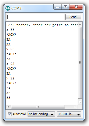
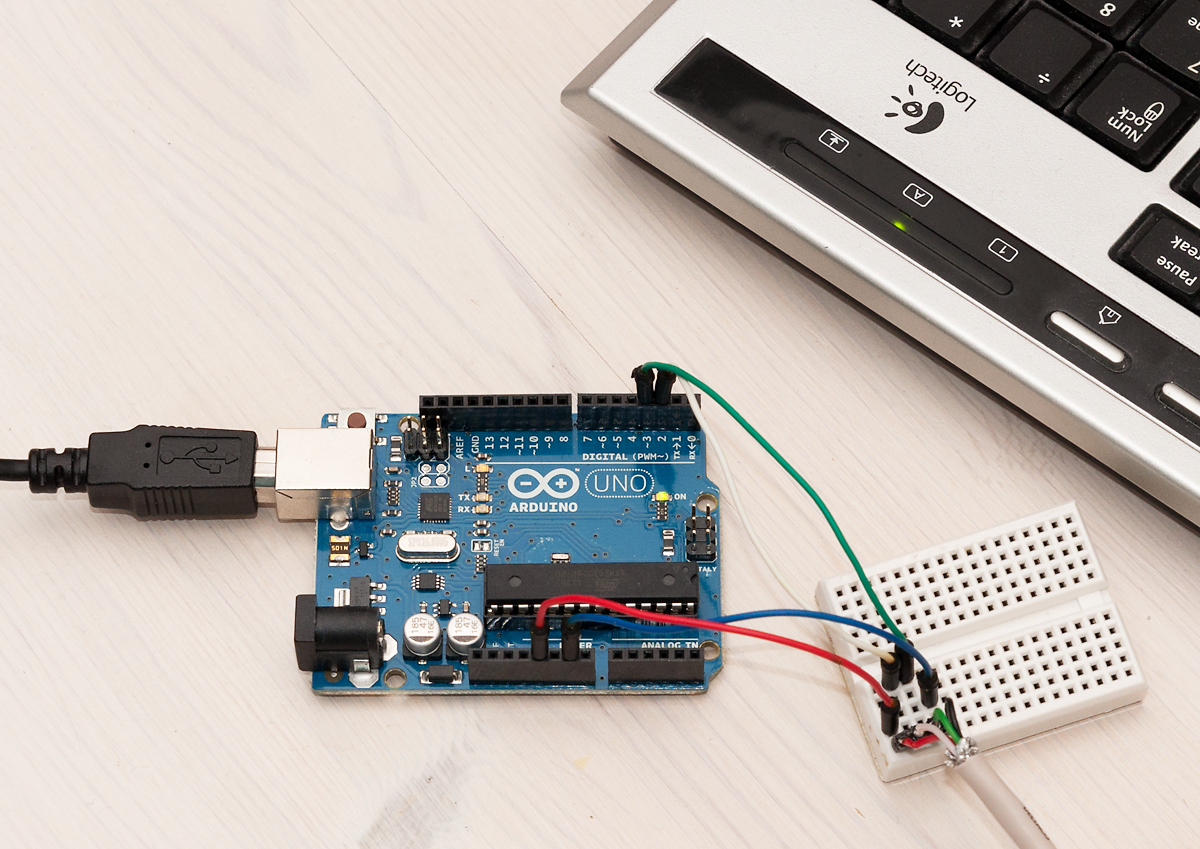
On the left you can see my Logitech keyboard responding to commands sent by the PS2tester sketch. Commands to be sent to keyboard are sent to Arduino over serial line in hex pairs (“FF”, “ED”, “02”, etc.), which should then be acknowledged by the PS/2 device during write with ACK, and after the write by sending back “acknowledge byte” FA. Data sent to and received from PS/2 device is echoed to serial line so we can see what is going on (sent bytes prepended with “>:”).
FF is a command to reset the keyboard, and we can see that both the ACK bit during write, and the FA message sent from keyboard are received successfully. After the keyboard has reset, it should also send “AA” to indicate successful initialization and test.
After reset there are commands to set keyboard LEDs (ED 02 turns on num lock LED) and F2 reads keyboard ID, which should (and does) result in two bytes AB and 83 from the keyboard (after FA, “acknowledge”, of course).
The whole code is just a bit over 200 lines, mostly because I decided to write helper functions and use plenty of comments along the way. Armed with this tool it should be easy to debug and play with PS/2 devices. Coming up next is a post on implementing a fully fledged PS/2 keyboard device with ATtiny!