UPDATED: 2015-02-15! This article has been very popular, so I’ve now updated all the benchmarks using the latest firmware and library versions. The scope has also been upgraded to a PicoScope 5444B with better resolution and bandwith than the earlier models. :)
Don’t try this at home! Shorting GND and VCC with a probe might fry your Pi and more!
Method and Summary of Results
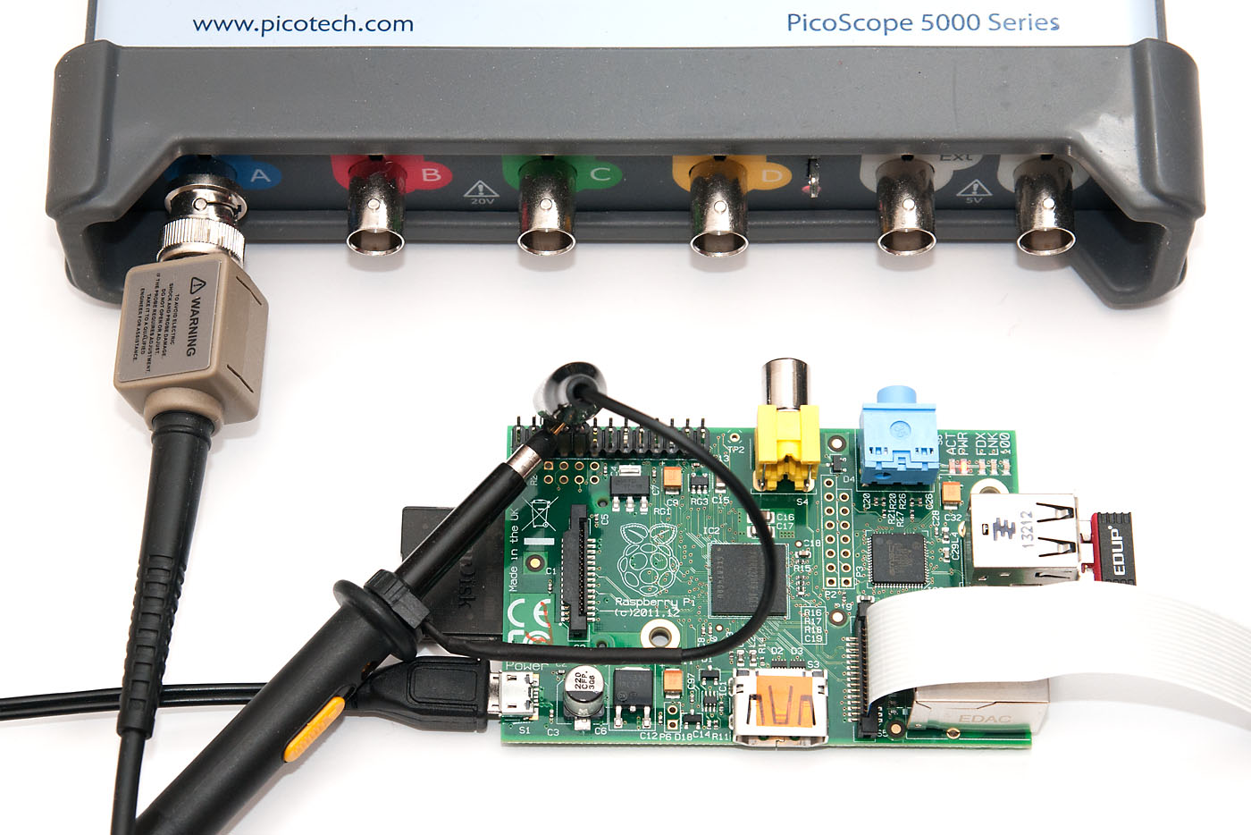
The basic test setup was to toggle one of the GPIO pins between zero and one as fast as possible. GPIO 4 was selected due to easy access and no overlapping functionality. This is basically the “upper limit” for any signalling one can hope to achieve with the GPIO pins – real-life scenarios where processing needs to be done would need to aim for some fraction of these values. Here are the current results:
Language
Library
Tested / version
Square wave
Shell
/proc/mem access
2015-02-14
2.8 kHz
Shell / gpio utility
WiringPi gpio utility
2015-02-15 / 2.25
40 Hz
Python
RPi.GPIO
2015-02-15 / 0.5.10
70 kHz
Python
wiringpi2 bindings
2015-02-15 / latest github
28 kHz
Ruby
wiringpi bindings
2015-02-15 / latest gem (1.1.0)
21 kHz
C
Native library
2015-02-15 / latest RaspPi wiki code
22 MHz
C
BCM 2835
2015-02-15 / 1.38
5.4 MHz
C
wiringPi
2015-02-15 / 2.25
4.1 – 4.6 MHz
Perl
BCM 2835
2015-02-15 / 1.9
48 kHz
Shell script
The easiest way to manipulate the Pi GPIO pins is via console. Here’s a simple shell script to toggle the GPIO 4 as fast as possible (add sleep 1 after both to get a nice LED toggle test):
In addition to the audio, video, network and USB connectors, the Raspberry Pi also has 26 GPIO pins. These pins also include an UART serial console, which can be used to log in to the Pi, and many other things. However, normal UART device communicate with -12V (logical “1”) and +12V (logical “0”), which may just fry something in the 3.3V Pi. Even “TTL level” serial at 5V runs the same risk.
So in this short tutorial, I’ll show you how to use a MAX3232CPE transceiver to safely convert the normal UART voltage levels to 3.3V accepted by Raspberry Pi, and connect to the Pi using Putty. This is what you’ll need:
Raspberry Pi unit
Serial port in your PC or USB to serial -adapter
MAX3232CPE or similar RS-232 to 3.3V logic level transceiver
5 x 0.1 uF capacitors (I used plastic ones)
Jumper wires and breadboard
Some type of female-female adapter
The last item is needed to connect male-male jumper wires to RaspPi GPIO pins. I had a short 2×6 pin extension cable available and used that, but an IDE cable and other types ribbon cable work fine as well. Just make sure it doesn’t internally short any of the connections – use a multimeter if in doubt!
The connections on Pi side are rather straightforward. We’ll use the 3.3V pin for power – the draw should not exceed 50 mA, but this should not be an issue, since MAX3232CPE draws less than 1 mA and the capacitors are rather small. GND is also needed, and the two UART pins, TXD and RXD.
A rather long wait ended today, when DHL dropped this little package off at work in the morning. I had placed my Raspberry Pi order in the first 24 hours when they started taking orders (or actually, registrations of interest) from RS Components, but it took about two months for me to receive the invitation to order, and three more weeks for the order to arrive.
Opening up the box, I was greeted with a very small computer, and two small leaflets, a quick start guide and a regulatory and safety pamphlet. The board is really quite small, just a few millimeters larger than a credit card. Two USB slots, HDMI, coaxial and stereo audio plugs and micro-USB for power, plus an ethernet jack.
I ran a quick test to see if everything worked. Initially, there was flicker on my projector (the only device with native HDMI input I currently have), but that turned out to be incompatibility with the HDMI switch I had – without it it worked just fine. I used the premade Debian image on a SD card and it worked perfectly.
There still seems to be a lot of traffic to my V-USB tutorials, so I thought I’d write a short follow-up post on USB keyboards. I already did a USB HID mouse post earlier, so you might want to check that out to understand a bit about HID descriptors and associated V-USB settings (in short, human interface devices send a binary descriptor to PC telling what kind of “reports” they send to the host on user activities).
As a basic setup, you’ll need a working V-USB circuit with one switch and one LED attached. Here, I’m using ATtiny2313 with the LED wired to PB0 and switch to PB1. The ATtiny is using 20 MHz crystal, so if you’re following my USB tutorial series and have that circuit at hand, remember to change that frequency in usbconfig.c before trying this out. Note the cool breadboard header I have, there will be more posts about that one to follow soon!
USB HID keyboard basics
A USB keyboard is a normal USB device, very much like a mouse, but it has an interrupt endpoint, which is used to send keyboard events to the host PC (instead of mouse movements). In this tutorial, I’m using a full “boot compliant HID” specification that can have up to six keys pressed down at a time. The bonus side is that these types of devices receive (at least on Windows, probably on Linux, not on OS X) keyboard LED state changes, so we can do cool things with our device, like I did in my USB password generator, where password generation is triggered by repeated CAPS LOCK presses.
To make the operating system recognize our device as HID keyboard, we need to make mostly the same changes to usbconfig.h as we did in my mouse tutorial. Here’s the overview of things you’ll probably need to change from my USB tutorial series:
Just a short post today, in case this will save someone’s day like it did my friend’s. He has a small Shuttle PC setup that suddenly stopped working about three weeks ago – the machine seemed to power up, but no picture came to screen. After some googling, he found out that the motherboard of this specific MB+case combo sometimes dies because of failed capacitors. And indeed, the biggest caps on the MB seemed to have a slight bulge on the top. So he called me if I could help him to replace them, to see if that would help.
The first thing to do was of course procure similar caps. The possibly failed models were three 1500 uF, 10V caps, so I got four new ones to replace them.
Removing the old caps
The first task was to remove the old capacitors from the motherboard. Because we wouldn’t be needing them, we used some force and cutters to first remove the capacitors themselves, and then set out to remove the legs with a solder iron. Unfortunately, the lead-free solder had a melting point beyond the number 7 tips of my Weller Magnastat, and no amount of heating was able to remove the legs!
Continuing from part 1 of this ATtiny2313 breadboard header with DipTrace -tutorial, I’ll now go through the PCB design. In DipTrace Schematic Editor, I used File->Convert to PCB (CTRL-B) to get the components and connections exported to PCB Layout tool. Like it’s schematic counterpart, also this tool is quite easy to use.
First I change the grid to 5 mil so each step is half of the 10 mil breadboard hole spacing. I then proceed arrange the components roughly to final layout, and add two 10-pin headers which will plug into breadboard. I then remove some component names which are not sorely needed, and change the location for the remaining ones to the center of the component.
Spacebar is again used to rotate components 90 degrees, and multiple items can be selected with ctrl+click. You probably notice that at some points of the video, the popup-menu options go outside the recording area. Sorry for that! However, I trust you’ll be able to find the correct option yourself if you look at the window that then pops up – usually it’s “xxx properties”, like component or pad properties that I open.
After getting the components more or less to their correct locations, I then draw a board outline (after adjusting the grid to a slightly fines 2.5 mil pitch). DipTrace also has an excellent “Replace pattern” option that lets me change the pattern used for a given component, which I used to replace crystal capacitor patterns with one that takes up less space on silk screen (the distance between pads stays the same, though).