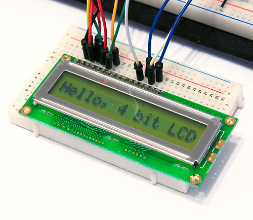
Since my brief journey to controlling LCD display directly with ATtiny2313 I purchased a display with Hitachi HD44780 compatible driver chip. The web is already pretty full of LCD tutorials and libraries, but most seemed to either skip details and rely on external libraries, or were just overly complex. So I decided it wouldn’t hurt to share the rather short (and functionally limited) versions I came up with.
8-bit mode
In 8-bit mode, you will be needing 8 pins for sending or reading a whole byte of data at once, and 3 control lines: enable (EN), register select (RS), and read/write (RW). Basic procedure is to prepare all other lines, and then pulse the enable line high for a short while in which LCD reads your command (when RW is low) or writes data (when RW is high). For control messages, RS line is low, and for writing letters, RS line is high.
I started with ATtiny2313 and used the 8 pins in port B as LCD data lines, and PD4, PD5, and PD6 as RW, RS, and EN, respectively. With such a setup, working write command became:
V-USB examples already contain an example of this, so I digged in to see what is different in usbconfig.h compared to the one we finished in my tutorial. It seems only a few things need changing:
USB_CFG_HAVE_INTRIN_ENDPOINT needs to be set to have an additional endpoint
USB_CFG_INTR_POLL_INTERVAL set to 100 ms instead of 10 in template
USB_CFG_IMPLEMENT_FN_WRITE is not needed, nor is …FN_READ (define both to 0)
Device ID and name need to be changed. I’ll just use the same ID as they did
USB_CFG_DEVICE_CLASS is set to 0, not 0xff
USB_CFG_INTERFACE_CLASS set to 3 instead of 0
USB_CFG_HID_REPORT_DESCRIPTOR_LENGTH defined to match the structure’s length
My local electronics shop Partco (arguably the best in Finland) had a great offer on 6-digit LCD displays. For 1€ a piece, I immediately bought one:
Once I had my hands on it, the reason for such a low price became apparent: There was no controller chip, only 50 pins and the knowledge that pin 1 was “common cathode” and the rest were for the segments. So I decided to see if I could get it work directly without a controller. And succeeded, read on to learn how!
After some googling, it became apparent that unlike LEDs, LCDs don’t like to have constant voltage applied over them, but instead need an AC source. They don’t draw current like LEDs, but instead work like capacitive planes, the segments with voltage difference between the segment and common cathode becoming visible. LCD segments get damaged if there is DC voltage for long periods of time, so the solution is to apply a square wave of about 100 Hz (some models like 30 Hz, others 200 Hz) to the common cathode and one in opposite phase to a segment to “light” it.
So if you use a MCU with 5V operating voltage to control the LCD, you first set the common cathode to 0V (ground) and a segment to 5V (VCC). After a while, you switch. This way, a segment experiences alternating voltages of +5V and -5V and does not get damaged. Finally, I found a great application note from Maxim that explained this really clearly and recommended 1k resistors for segments and none for the common cathode. I was good to go! Here’s a rough schematic:
Now all we need is a bit of code! I had a ATtiny2313 wired with a 12 MHz crystal, so I decided to use the 16-bit timer 1 which would be called 200 times a second to create a 100 Hz square wave. With a prescaler of 8, timer 1 gets incremented 1.5 million times a second, so with OCR1A set to 7 500 (625 * 12) we get what we want:
All right. Now that we got the basic USB code working in part 3, it’s time to wrap things up in this tutorial series. This fourth section will explain how to send data from your device to PC and also the other way around. I may later do a fifth part on how to make a USB HID device like a keyboard or mouse, so if you haven’t already, I’d recommend subscribing to the RSS feed to get updates.
Sending data from device to PC
If you look carefully at our command-line client code, you probably noticed that the control messages sent to toggle the led are of type USB_ENDPOINT_IN and we have a 256-byte buffer in place to receive any data the device sends. So far we have not received any data and the return value stored in nBytes has been zero. Let’s change that.
If you read through the documentation in usbdrv/usbdrv.h, more specifically the comments for usbFunctionSetup() we used to toggle our LED on device side, you can see that there are two ways to return data from usbFunctionSetup():
Set the global pointer usbMsgPtr to a (static RAM) memory block and return the length of data from the function
Define usbFunctionRead() function to do it yourself
We will be using the first method. First we define an additional message USB_DATA_OUT and a static buffer to store the data we want to send from device to PC:
This is the third part of my USB tutorial for ATtiny2313 and V-USB library. In the second part we got the breadboard setup more or less covered, and now is the time for actual code! This will most likely be the longest of the three parts, so let’s get started.
Adding V-USB as a part of your project
First, we will download the latest version V-USB library from OBdev. Head to the Downloads-section and get the latest .zip – I got vusb-20120109.zip.
Unzip the archive and copy the usbdrv subfolder to your project folder (the whole folder, not just contents). Go to the subfolder and make a copy of usbconfig-prototype.h with the name usbconfig.h. Locate the #define lines for IO port and port bits and clock rate, and update them as necessary to reflect our configuration where D+ is in PD2 and D- in PD3 and clock rate is 12 MHz:
It’s also a good idea to ensure that V-USB tells the computer that it is powered via USB (i.e. not self powered) and takes maximum of 50 mA of power (defaults in my version is USB power, 100 mA max.):
We will be using OBdev’s licenced vendor and device IDs, so they don’t need to be changed (note that this also means my tutorial will fall under GPL, including the schematic in part 2). But we do want to customize the vendor name and device name (note the backward slash in vendor name string used to split the #define to two lines so it fits into this blog post):
This is the second part of my USB tutorial for ATtiny2313 and V-USB library. In the first part we learned how to get 3.3V from USB to power our circuits. In this part, we will expand our setup with following parts:
Larger breadboard and additional jumper wires
ATtiny2313
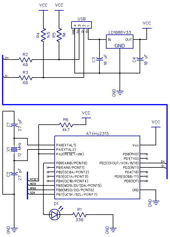
12 MHz crystal oscillator
Two 27 pF ceramic capacitors to stabilize the crystal
Two 68 Ω resistors between USB data lines and the microcontroller pins
1 MΩ pullup resistor for D+ and 1.5 kΩ pullup for D-
6-pin header for programming the ATtiny and 4.7 kΩ pullup for reset pin
Update: Some people have noted that the setup I’m using here runs ATtiny2313 at 12 MHz with only 3.3V VCC, which is outside the specified range (frequencies over 10 Mhz require 4.5V or more). I’ve never had any problems, and many others have succeeded with this setup, but if you encounter persistent problems, I suggest you to power the ATtiny2313 straight from 5V of the USB line and use zener diodes on D+ and D- lines to drop their voltage, as is done in my later tutorial with the ATtiny85 microcontroller.
Breadboard setup
This time I will not walk you through every connection. Instead, I’ll just outline the steps needed and show the pictures of end result. Here is the schematic we’re building: