DIY Bluetooth Keyboard Breakout for $10
You could get an excellent Bluetooth keyboard controller from Adafruit called Bluefruit EZ-Key which allowed super easy creation of projects that sent keyboard presses (for example a gamepad) just by connecting some switches to the pins. However, the EZ-Key cost $20 and is now discontinued. And in any case, Bluetooth-capable devboards are now available from AliExpress for a few dollars, so $20 today feels on the steep side. “Could it be done cheaper?” I wondered…
I have honestly about a dozen cheap wireless devboards lying around, many based on ESP8266 which only have Wi-Fi, but some also with ESP32 which includes Bluetooth. I spent some time trying to configure a Chinese ZS-040 serial Bluetooth module to function as a keyboard, but the AT command set was a very small subset of what the similar HC-05 / HC-06 modules have. After an evening of trying, I decided to give up on that. There are instructions how to flash HC-05 modules with RN-42 firmware to get Bluetooth HID capability, but it will require quite a few steps.
I also took a look at esp32_mouse_keyboard project, but for some reason or another, abandoned that avenue. Don’t recall if there were obstacles or the project was still incomplete a year ago, might also be that the ESP32 only had BT LE which technically didn’t support HID (Human Interface Device). Throw me a comment if you have that working!
Meanwhile, another idea dawned to me:
A Cheap Bluetooth Keyboard Must Contain A Bluetooth Module
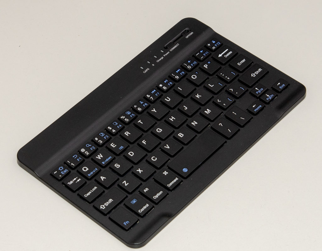
Enter the wonders of AliExpress: While you cannot source an easy BT keyboard module from US under $20, you can get a full mini Bluetooth keyboard for $9.50 (at time of writing) including postage! This package ought to contain:
- A fully compliant Bluetooth board that pairs with iOS, Android and PC devices
- Full functioning keyboard and case
- Presumably, a battery and a way to charge it
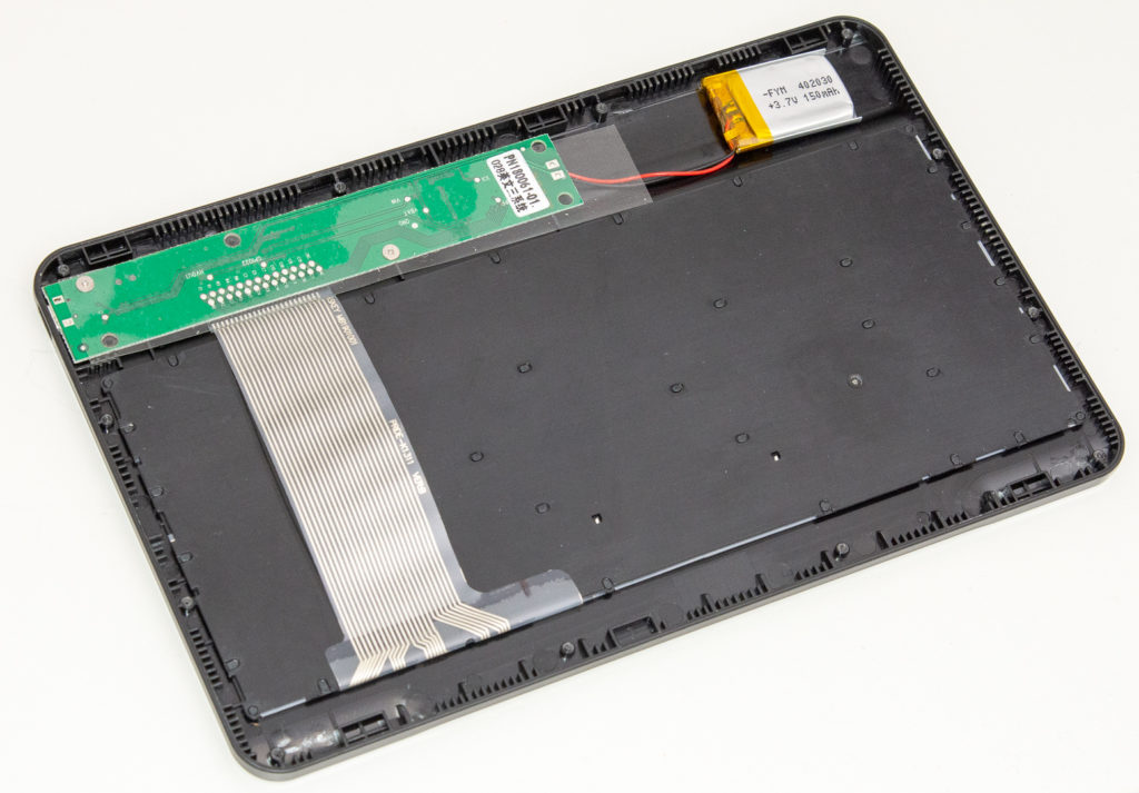
Sounds a too good deal to be true? Well, let’s find out! The keyboard has a solid metal backplate that is easily screwed open with micro cross head screwdriver. Once inside, it reveals a very professional layout with a flat ribbon cable (or “FCC cable”) coming from the mechanical part into the controller module, And a small (most likely LiPo) battery.
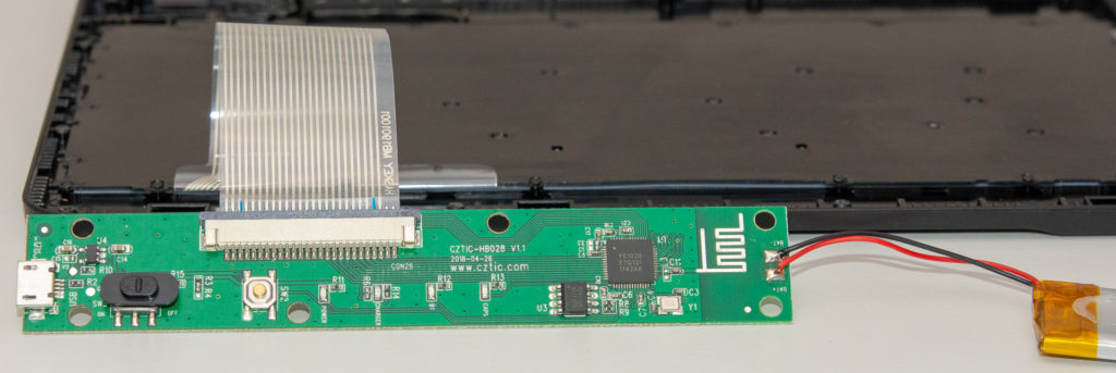
Taking the tape off and turning the board around reveals a bit spacious, but very professional looking PCB with clear markings. There are easily usable on/off switch and connect button on the PCB, a connector for the keyboard switches, and obviously some kind of microcontroller wired to the connector, as well as another smaller chip that is most likely a voltage regulator or charging chip.
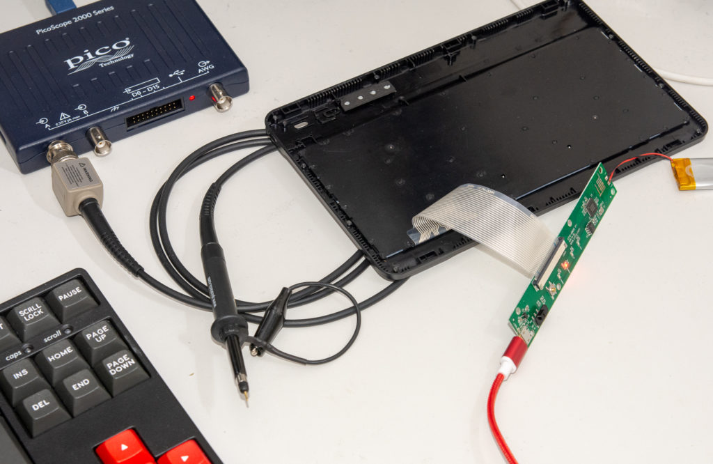
I Googled around to find out if the “YC1026” MCU would have a datasheet to help me along the way, but unfortunately I only got Chinese web pages (most likely the manufacturer) without any documentation. Time to dig out my trusty Picotech 2000 scope and do some old-fashioned reverse engineering!
I connected the board to USB power so I would have GND levels aligned, that way I could ditch the ground connection from the probe and use just the sharp tip. Good thing I had my Picoscope around, as I’d borrowed my multimeter to a friend.
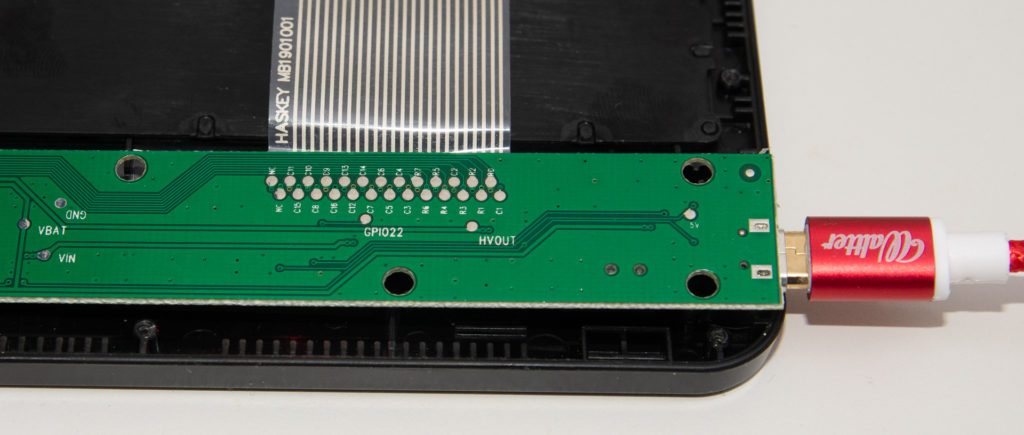
Firing up the Picoscope software, I quickly checked that GND traces are about 0 volts which turned out to be true once USB was plugged in. The battery was in good shape giving out around 4 volts. The board is most likely a 3.3V MCU. Turning around the PCB gives a nice access to the connector pins using my probe:
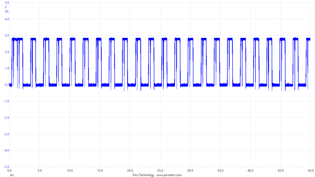
The markings are quite straightforward: There are few NC (Not Connected) pins, and then “row” pins labeled R0-R7 and “column” pins running from C1 to C15. Quick testing showed that the Rx pins were by default on HIGH (around 3.7V) whereas Cxx pins showed a square wave of some sort. I initially thought there was maybe some transmission protocol coming from the keyboard, but then in occurred to me that this would most likely be too complicated. It’s more reasonable the mechanical keyboard is just a set of switches with no logic circuits. And since it’s wasteful to invent new schemes for wiring, it most likely uses a matrix keyboard scanning algorithm.
Matrix Keyboard Scanning
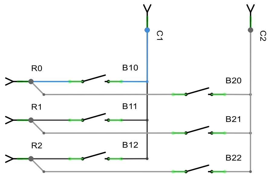
“What is the matrix?” I hear you ask. Don’t be afraid, Neo, I’ll tell you! If you would like to wire for example six buttons to a microcontroller, you usually would set six pins as inputs with a pullup resistor, then wire each pin to a button that is connected to ground on the other end. When you press a button, the pin is connected to ground, and despite weak pullup that usually keeps logic level “high”, the pin goes “low”. Now imagine that instead, you arrange the six buttons in two columns and three rows, and connect all buttons to one of two “column pins” and one of three “row pins”:
Now instead of having fixed GND connections on one end, you can control C1 and C2 using your MCU. You still set R0, R1, and R2 as inputs with pullup, but normally keep C1 and C2 inactive (e.g. set them as inputs without pullup). When you want to read buttons B10-B12, you switch C1 into output mode and set it to zero/low. Now C1 becomes “GND” and you can read R0-R2 to see which buttons in the first column are pushed (i.e. in connected state). Once you have that, you reset C1, and proceed to set C2 as GND and read B20-B22 in a similar manner.
With 2×3 matrix you use only five pins for six buttons! That may not sound like an improvement, but with 8×8 matrix you’d only need 8+8=16 pins for 8*8=256 inputs — saving a reasonable 240 input pins. Now take a look again at the connector panel:
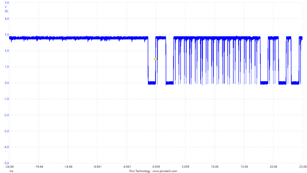
The setup here is 8 rows (R0-R7) that are usually kept “high” by pullup resistors, and read by switching C1-C15 as GND one by one. Here is for example C1 being set to GND:
Row pins R0-R7 are by default high, but once I pressed arrow right (wired between R0 and C1 as this example will show) on the bluetooth keyboard, you can see R0 going down. After some initial changes (most likely there is some interrupt routine conserving power when no keys are pressed) the pattern will match the pattern output to C1 pin — as no other keys are held down, the R0 is basically connected to C1.
Emulating Keypresses
The keyboard only has about 60 buttons, so 8×13 = 104 matrix connections are all not used. It also seemed the Cxx ports are “low” way more than 1/13th of the time as they would be in standard matrix scanning, so there might be something additional going on here. But we don’t need to worry about that if we only want to send keypresses using the board. Now that we know the logic, the procedure is simple:
- Find out what row-column intersection the desired key/switch is connected to (as seen above, right arrow was C1-R0)
- To send that key “manually” without the mechanical keyboard, just short the corresponding pins
You can do step one with an oscilloscope, multimeter or even just LED and resistor in series. But even easier is the “short them and see what happens” approach — just connect a pair row and column pins and see what keypress is sent, there’s a handy tool at https://www.keyboardtester.com/ that shows what keys are pressed. By the way: the charging LED was annoyingly bright so I used a black marker on that one in order not to go blind while debugging!
Word of caution: Be very careful not to short two Cx pins, as the MCU is driving voltage in them, you may damage or even cripple your (relatively cheap) board that way!
Here’s a couple of the first columns (R5-R7 are not connected to them) I mapped out. Note that some characters will differ based on your keyboard layout, what is semicolon below may be “ä” on your machine:
| R0 | R1 | R2 | R3 | R4 | |
|---|---|---|---|---|---|
| C1 | Right | ||||
| C2 | Down | Space | |||
| C3 | Shift | Backspace | |||
| C4 | Left | Up | |||
| C5 | . (period) | ; (semicolon) | Enter |
One additional set of keys which may prove really handy are the numbers 0 to 9, as Windows and iOS both want you to type a series of numbers to initially pair the KB. Note that due to key repetition, it might be really frustrating exercise to pair the board with a piece of wire (it’s very easy to “type” 111 instead of 1), so I suggest you save the mechanical part of this keyboard for this task!
- 1: R6 / C9
- 2: R6 / C16
- 3: R6 / C13
- 4: R6 / C12
- 5: R7 / C12
- 6: R7 / C14
- 7: R6 / C14
- 8: R6 / C7
- 9: R6 / C6
- 0: R6 / C5
A relatively fast way to map out these keys: Press the desired key down, and use scope, multimeter or LED to find out which Rx pin went to GND (part-time). Then position one end of a jumper wire on that pin, and short Cxx pins with the other end in succession, until you see the desired keypress sent from the KB. Easy!
Conclusions and Future Work
Now you are armed to send any Bluetooth keyboard keypress to the device of your choice (pair first!) just by shorting a couple of pins. I’m planning use this to make a $15 Bluetooth pedal that will turn pages for me when playing the piano and reading sheet music on an iPad (most sheet music SW work with Bluetooth keyboards and $100 page turning pedals that basically just really expensive arrow keypads).
If you want a permanent solution using this board, you can just solder a couple of wires on the board and you are done. However, if you want a more prototyping friendly solution, I’d recommend getting a FPC/FFC adapter for a couple of dollars that will give you easy to handle headers instead of tiny points of solder or ends of connector cable. For example this one on AliExpress should do the job well. You’ll also need to order some FFC (or FPC) cable — based on my measurements this is the 1.0mm pitch cable, also available in packs of 5-10 for a dollar (except for the rare one used by Raspberry Pi cameras which has odd number of lines and is ridiculously overpriced).
PS. If you position the cable correctly, and don’t need the full range of pins, you can do with a flat cable that has less lines — I only need to short edgemost R0 and C1 to send “arrow right”, so I got a pack of 12-pin cables and an adapter to that in addition to the full 26p versions. A few adapters and a dozen cables cost me less than a good latte would so I’m not trying to optimize too much.
To summarize, we learned how to turn a sub $10 bluetooth keyboard into a DIY component for electronics projects. Compared to reflashing a $3 HC-05 board, this is somewhat more expensive, and the board is twice as large. But you get some concrete benefits as well:
- Firmware already in place and plays well with Windows (tested), iOS (tested) and Android (was too lazy to test)
- LiPo battery to power the board autonomously
- Charging capability for the battery
- Power switch, connect button
- Some LEDs to indicate power on event, connection, etc.
Happy hacking!
