Fast DDS with ATmega88
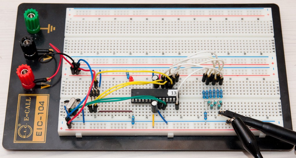
I’m planning to make some RFID hacking in near future using 150 kHz tags. Since I don’t have a signal generator, I decided to go where quite many people have gone before and build myself one, more specifically a DDS. Instead of just taking a complete project from the net, I thought this would be a good way to learn a bit of AVR assembly programming, and manual D/A (digital to analog) conversion using R-2R ladders. Here’s what I built:
I’m skipping the schematic to save some time – basically it’s a ATmega88 with 6-pin programming header, power, a 16 MHz crystal (other frequencies also work, lfuse for this setup if 0xFF) and a red LED that is not used. The R-2R ladder is wired with white jumper wires to PB0-PB5 (it’s a 6-bit DAC) so that PB0 is the “least significant bit” and PB5 the most significant one. Read on for details.
R-2R ladder in brief
The analog to digital converter in this project is a R-2R ladder built from 10 kOhm (R) and 20 kOhm (2R) resistors. By providing GND/VCC to the points a_{0}..a_{n-1} (see the diagram below), a voltage between GND and VCC * (1-1/2^n) can be seen at V_out (in this example n=6 and V_out can reach 63/64 of VCC).

(from Wikipedia R-2R article, licensed under creative commons, author Lsibilla)
If you want to check that it actually works, you can start with 1-bit version and easily see that when a_0 is 0V/5V, V_out is 0V/2.5V (5*(1-1/2^1)). If you derive a Thevenin equivalent circuit for this, you get one with 0/2.5V voltage source and 2R resistor in series. By adding another bit to this equivalent circuit, you can verify that the 2-bit version works also and it’s Thevenin equivalent resistance is also 2R – and by induction, you see that after any number of bits, the resistance stays at 2R and voltage is:
1/2 * a_{n-1} + 1/4 * a_{n-2} + … + 1/2^n * a_0
Generating a sine wave using C
So with our 6-bit R-2R DAC, setting just PB0 will make V_out 1/64 of VCC. PB1 has twice that impact, PB2 twice more and so on, and finally PB5 contributes 1/2 of VCC to V_out. Effectively this means that the 6-bit binary value we write into PB0..PB5 is converted to analog voltage level, and we can generate a sawtooth wave with very short piece of code:
#include <avr/io.h>

#define DAC_PORT PORTB
#define DAC_DDR DDRB

int main() {
    unsigned char counter;

    DAC_DDR = 0x3f; // 6 bit

    while(1) {
        DAC_PORT = counter++;
    }

    return 1;
}
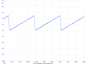
Note that topmost 2 bits of our counter will be gone to waste as an external crystal is used and it’s in PB6-PB7. Verifying with scope confirms that we get a 62.5 kHz waveform (meaning we have 64 steps of 4 clock cycles with 16 MHz crystal: 16M / 64 / 4 = 62.5k):
To make a sine wave, I have precalculated a 256-step table waveform[] that stays within 0..63 required by our application. Only other thing we need to change is the inner loop:
unsigned char waveform[256] = {
32, 32, 33, 34, 35, 35, 36, 37, 38, 39, 39, 40, 41, 42, 42, 43,
44, 44, 45, 46, 47, 47, 48, 49, 49, 50, 51, 51, 52, 52, 53, 54,
54, 55, 55, 56, 56, 57, 57, 58, 58, 59, 59, 59, 60, 60, 60, 61,
61, 61, 62, 62, 62, 62, 63, 63, 63, 63, 63, 63, 63, 63, 63, 63,
63, 63, 63, 63, 63, 63, 63, 63, 63, 63, 63, 62, 62, 62, 62, 61,
61, 61, 60, 60, 60, 59, 59, 59, 58, 58, 57, 57, 56, 56, 55, 55,
54, 54, 53, 52, 52, 51, 51, 50, 49, 49, 48, 47, 47, 46, 45, 44,
44, 43, 42, 42, 41, 40, 39, 39, 38, 37, 36, 35, 35, 34, 33, 32,
32, 31, 30, 29, 28, 28, 27, 26, 25, 24, 24, 23, 22, 21, 21, 20,
19, 19, 18, 17, 16, 16, 15, 14, 14, 13, 12, 12, 11, 11, 10, 9,
9, 8, 8, 7, 7, 6, 6, 5, 5, 4, 4, 4, 3, 3, 3, 2,
2, 2, 1, 1, 1, 1, 0, 0, 0, 0, 0, 0, 0, 0, 0, 0,
0, 0, 0, 0, 0, 0, 0, 0, 0, 0, 0, 1, 1, 1, 1, 2,
2, 2, 3, 3, 3, 4, 4, 4, 5, 5, 6, 6, 7, 7, 8, 8,
9, 9, 10, 11, 11, 12, 12, 13, 14, 14, 15, 16, 16, 17, 18, 19,
19, 20, 21, 21, 22, 23, 24, 24, 25, 26, 27, 28, 28, 29, 30, 31
};

// ... in main() inner loop:
DAC_PORT = waveform[(counter++) & 0xFF];
We can again confirm that this actually works:
Adding frequency control
Final step before diving into assembly version is to add a more fine-grained control over the frequency than just swapping a new crystal in place. This will be done using fixed-point arithmetic, where we have a 16-bit counter that will use upper byte for storing the integer part of waveform counter, and lower byte for fractional part. Here’s the inner loop refactored into a separate function:
void cloop(uint16_t step) {
    uint16_t counter = 0;

    while(1) {
        counter += step;
        DAC_PORT = waveform[counter >> 8];
    }
}
Easiest way to understand the above code is to consider a few examples. Let’s say we use step value 256, i.e. 0x0100. Here are the first few iterations:
| # | counter | counter >> 8 |
|---|---|---|
| 1 | 0x0000 | 0x00 |
| 2 | 0x0100 | 0x01 |
| 3 | 0x0200 | 0x02 |
It’s easy to see that by using 0x0100 the waveform is advancing by 1 per iteration. Now if step would be 0x0200 it would advance by 2, and so on. What about values less than 256? Let’s use half of that, 0x0080:
| # | counter | counter >> 8 |
|---|---|---|
| 1 | 0x0000 | 0x00 |
| 2 | 0x0080 | 0x00 |
| 3 | 0x0100 | 0x01 |
| 4 | 0x0180 | 0x01 |
| 5 | 0x0200 | 0x02 |
| 5 | 0x0280 | 0x02 |
Wee see that the lower byte of counter works as a fractional part, “overflowing” to upper byte every second iteration, and causing the waveform to advance 1 step every other iteration. If we had used 1/4 * 256 as step value, we’d advance every 4th iteration. In general, with step value X the waveform will advance X/256.0 per iteration, allowing us 1/256th of a step resolution.
If we want to achieve a certain frequency, we need to calculate a correct step value for our function. When I compiled the function it turned out that each iteration took 11 clock cycles. If we advance the waveform by step/256 (i.e. by one if step=256) each iteration, the effective frequency would become (remember there are also 256 steps in the waveform):
Freq = F_CPU / 11 / 256 * (step/256)
Solving this for step we get:
step = Freq * 256 * 256 * 11 / F_CPU
If we want a 150 kHz signal, the step would be 6758, or 0x1A66. This can be confirmed with the oscilloscope, or if you don’t have one, a simple multimeter with frequency measurement functionality will do. Mine gave 149.9 kHz. The math works!
Increasing resolution with assembly
If you look at the output from our C function, you’ll notice it looks plain ugly. The reason is that in 11 clock cycles, we only have less than 10 samples on average per wave. This results in very jagged sine wave. By writing the loop in assembly language, this can be squeezed to 7 clock cycles per iteration, giving us over 15 samples per wave at 150 kHz. This is not too much but the output does become cleaner:
Here is the 1:1 cloop(step) compatible version, asmloop(step):
#include <avr/io.h>

.section    .text

.extern     waveform

; extern void asmloop(uint16_t step);
.global asmloop

#define     I   r18
#define     FIX r19

#define     STEP_H r25
#define     STEP_L r24

asmloop:
    clr     I
    clr     FIX
    ldi     r30, lo8(waveform)
    ldi     r31, hi8(waveform)

; only works if lo8(waveform) == 0
loop:
    add     FIX, STEP_L             ; 1 clock
    adc     r30, STEP_H             ; 1 clock
    ld      I, Z                    ; 2 clocks
    out     _SFR_IO_ADDR(PORTB), I  ; 1 clock
    rjmp    loop                    ; 2 clocks
If you haven’t seen AVR/gcc assembler code before, here’s a short walkthrough:
- Semicolon (;) is used for comments
- We use
#include <avr/io.h>to get the handyPORTBand other definitions for the ATmega88 - C-side variables are introduced using
.extern - ASM-side functions (and variables) are declared using
.global - Defines can be used to create shorthands for AVR registers r0-r31
- Registers r0, r18-r27 and r30+r31 (the last two collectively forming the “Z” register) can be used without the need to restore their contents afterwards (we don’t return from our method so we could use others too)
- We define r18 as I to hold the value that is copied from
waveformtoPORTB FIXstores the fractional part of our fixed-point counter- Command-line parameters are passed in registers r24/25 (low/high byte), r22/r23 and so on – we use the only parameter,
stepdirectly from r24/r25 (defines STEP_L/STEP_H) - The 16-bit memory address of
waveformis loaded to r30:r31 aka. “Z” register. The code takes advantage of the fact that as we don’t have any other memory variables in our program, lower byte (i.e. r30) should be 0, so it can double is integer part of “counter”, saving us additional clock cycles - The inner loop first adds the fractional part (if it overflows, carry flag is set), then the integer part (plus carry flag), and then just copies the byte from
waveformtoPORTB PORTBdoes not work directly, but we need to use_SFR_IO_ADDRmacro with it when outputting data
If we would’ve wanted to return any values, that would be done using r24:r25, the same registers that are used to pass the first parameter to a function. The assembly function needs to be also introduced on C side of the code so the compiler knows what to expect:
extern void asmloop(uint16_t step);With that done, we’re ready. Note that the 7 clock cycle inner loop is 22 % faster than Jesper Hansen’s DDS routine that is widely used in the net. This is achieved through using 16-bit (8.8) step value instead of 24-bit (8.16) one (-1 clock), and by using SRAM instead of program memory to store the waveform (-1 clock).
You can download the full project source with a makefile that you can use to compile and flash the project (make generator.flash). If there’s demand, I can also make a schematic, but the picture and schematic of R-2R ladder is probably enough for most.
Useful links
I haven’t yet found any outstanding links on AVR assembler – I’ve coded a fair share of x86 assembly in my youth so ATmega88 data sheet’s instruction set summary combined with Jesper’s DDS code and code outputted by generator.c (gcc -S -O2 -mmcu=atmega88 generator.c) was just enough to create this article. The best one I found with quick googling was this:
http://www.avr-asm-tutorial.net/avr_en/beginner/index.html
A good summary on register use and calling conventions is available here:
What would You like me to cover?
I noticed that after my USB password hack, the number of subscribers passed the 100 mark. I would be interested to hear what kind of things you’d like me to cover in the future. So if you have a subject in mind you’d like to read more about, send me an e-mail at jokkebk … iki.fi or post a comment!


