Code and Life

Programming, electronics and other cool tech stuff

Supported by

Supported by Picotech

Driving an LCD display directly with ATtiny

My local electronics shop Partco (arguably the best in Finland) had a great offer on 6-digit LCD displays. For 1€ a piece, I immediately bought one:

Once I had my hands on it, the reason for such a low price became apparent: There was no controller chip, only 50 pins and the knowledge that pin 1 was “common cathode” and the rest were for the segments. So I decided to see if I could get it work directly without a controller. And succeeded, read on to learn how!

After some googling, it became apparent that unlike LEDs, LCDs don’t like to have constant voltage applied over them, but instead need an AC source. They don’t draw current like LEDs, but instead work like capacitive planes, the segments with voltage difference between the segment and common cathode becoming visible. LCD segments get damaged if there is DC voltage for long periods of time, so the solution is to apply a square wave of about 100 Hz (some models like 30 Hz, others 200 Hz) to the common cathode and one in opposite phase to a segment to “light” it.

So if you use a MCU with 5V operating voltage to control the LCD, you first set the common cathode to 0V (ground) and a segment to 5V (VCC). After a while, you switch. This way, a segment experiences alternating voltages of +5V and -5V and does not get damaged. Finally, I found a great application note from Maxim that explained this really clearly and recommended 1k resistors for segments and none for the common cathode. I was good to go! Here’s a rough schematic:

Now all we need is a bit of code! I had a ATtiny2313 wired with a 12 MHz crystal, so I decided to use the 16-bit timer 1 which would be called 200 times a second to create a 100 Hz square wave. With a prescaler of 8, timer 1 gets incremented 1.5 million times a second, so with OCR1A set to 7 500 (625 * 12) we get what we want:


TCCR1B |= (1 << WGM12); // configure timer 1 for CTC mode
TIMSK |= (1 << OCIE1A); // enable CTC interrupt for timer 1

OCR1A = 625 * (F_CPU/1000000L); // 200 Hz with prescaler 8

sei(); //  enable global interrupts

TCCR1B |= (1 << CS11); // start timer 1 at clk/8

The timer routine itself is simple:

  1. First toggle the common anode at PD6
  2. If PD6 is high, a low value in pins PB0-PB2 will translate to a visible segment
  3. If PD6 is low, a high value in pins PB0-PB2 will translate to a visible segment
  4. Every 200 calls (once per second) increment “segments” variable

This basically gives me a binary counter from 0 to 7 with three segments:


ISR(TIMER1_COMPA_vect) { // 200 Hz timer to generate 100 Hz square wave
    static uint8_t cathode = 0, segments = 0, counter = 0;

    PORTD ^= (1<<PD6); // toggle cathode voltage
    cathode = !cathode; // toggle cathode indicator

    if(cathode == 0) { // cathode at 0V - high bits visible
        // segment bit LO/HI -> pin LO/HI
        PORTB = (segments & SEG_PINS) | (PORTB & ~SEG_PINS);
    } else {
        // segment bit LO/HI -> pin HI/LO
        PORTB = (~segments & SEG_PINS) | (PORTB & ~SEG_PINS);
    }

    counter++;

    if(counter >= 200) {
        counter = 0;
        segments++;
    }
}

Quick check with an oscilloscope shows that PD6 and PBx really toggle between same and opposing phase (here’s a moment when they are in opposing phase, “LCD on” – note that I’m using 1:10 probes here):

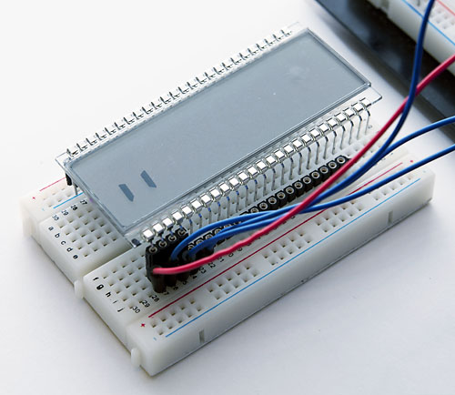
And what do you know: It actually works! I had to use some pin headers to avoid sinking the LCD too firmly to my breadboard.

It was a nice hack, but using 50 pins of a microcontroller or alternatively something like 7 shift registers seemed an overkill. But it’s good to know how an LCD works in any case. Here’s the complete source file if you want to try it out (at your own risk of course :).

11 comments

Tuhnu:

I’d change that “(at your own responsibility of course :)” to “(at your own risk of course :)”. ;)

Nice hack. :)

jokkebk:

@Tuhnu Thanks. Good idea, that sounds better. :)

MSubhanH:

I have a question Joonas, if I had to run this LCD by ATtiny and instead of one LCD, I had multiple LCDs of this kind that I need to switch between from a pc GUI, how would I go about it? It seems there comes the problem of having multiple while(1) loops in the code – one for polling the USB requests and the other to run timer for PWM. Is there an easier way to achieve this instead of threading or operating systems?

Joonas Pihlajamaa:

Timer interrupts are the only rather simple method of multitasking apart from actual DIY multitasking (doing different things in a single while loop). There are some good tutorials for that in AVR Freaks forums.

MSubhanH:

Well as a test code, if I call the usbPoll() again in secondary the loop like as in the following code:

USB_PUBLIC uchar usbFunctionSetup(uchar data[8]) {
usbRequest_t *rq = (void *)data; // cast data to correct type

if(rq->bRequest == 1)
{
while(rq ->bRequest == 1)
{
PORTA ^= 1 <bRequest == 0)
{
PORTA &= ~1;
PORTD &= ~(1 <bRequest == 3)
{
PORTD |= 1 << PIND6;
return 0;
}

return 0; // should not get here
},

shouldn't the LED keep blinking as long as I don't send any other command other than LED ON 1 ? It ceases to do that, it blinks for a little while and then exhibits an error.

MSubhanH:

Wrong code sent previously,,sorry for that.

USB_PUBLIC uchar usbFunctionSetup(uchar data[8]) {
usbRequest_t *rq = (void *)data;

if(rq->bRequest == 1)
{
while(rq ->bRequest == 1)
{
PORTA ^= 1 <bRequest == 0)
{
PORTA &= ~1;
PORTD &= ~(1 <bRequest == 3)
{
PORTD |= 1 << PIND6;
return 0;
}

return 0; // should not get here
}

MSubhanH:

Don’t know why, but the code is not uploading properly.

Joonas Pihlajamaa:

Doesn’t matter, I don’t think you can have a while-loop of any significant length in usbFunctionSetup, I think you need to get a response to the request quite quickly over USB. Furthermore, the while loop seems like something that will run forever, because you don’t change it within the for loop.

Right way to do blinking is in the while(1) loop of the main method, something like this (in pseudocode):

// set up interrupts to trigger every X ms

while(1) {
// call USB poll

if(one_second_elapsed() && do_blink == 1) {
PORTD ^= 1 << SOME_PIN; // you would also need an additional // variable to prevent this running again // until next second has elapsed } if(another_activity_due()) do_something_very_quickly(); } So one iteration of main loop is always quite quick, and you just use variables and timer triggers etc. to control what things are handled in each iteration.

MSubhanH:

Thanks a lot Joonas for your quick reply. I’ll try implementing this methodology and will then update you.

Rankku:

I remember to have noticed these among the “tarjouserät” sometime, but they seem to have got rid of this stock by now. Apparently I don’t go there often enough, as I never bought one. But on the other hand, only one common doesn’t sound very attractive. With TWO separate commons this would have been an interesting match for a Mega169 capable of driving 4×25 segments.

Joonas Pihlajamaa:

You’re in luck, as a LCD with this many pins is just waste of energy for any practical project (unless you plan to build something for mass production :), 4-pin programmable LCDs with their on logic chip are 10x more useful than this one… It’s fun for learning about LCDs, but that is about it.