Code and Life

Programming, electronics and other cool tech stuff

Supported by

Supported by Picotech

AVR ATtiny USB Tutorial Part 2

This is the second part of my USB tutorial for ATtiny2313 and V-USB library. In the first part we learned how to get 3.3V from USB to power our circuits. In this part, we will expand our setup with following parts:

  • Larger breadboard and additional jumper wires
  • ATtiny2313
  • 12 MHz crystal oscillator
  • Two 27 pF ceramic capacitors to stabilize the crystal
  • Two 68 Ω resistors between USB data lines and the microcontroller pins
  • 1 MΩ pullup resistor for D+ and 1.5 kΩ pullup for D-
  • 6-pin header for programming the ATtiny and 4.7 kΩ pullup for reset pin

Update: Some people have noted that the setup I’m using here runs ATtiny2313 at 12 MHz with only 3.3V VCC, which is outside the specified range (frequencies over 10 Mhz require 4.5V or more). I’ve never had any problems, and many others have succeeded with this setup, but if you encounter persistent problems, I suggest you to power the ATtiny2313 straight from 5V of the USB line and use zener diodes on D+ and D- lines to drop their voltage, as is done in my later tutorial with the ATtiny85 microcontroller.

Breadboard setup

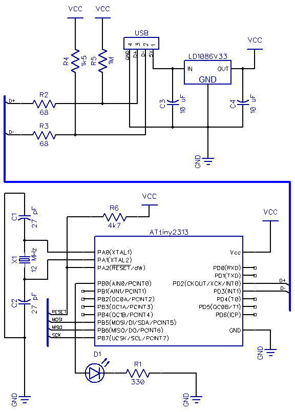
This time I will not walk you through every connection. Instead, I’ll just outline the steps needed and show the pictures of end result. Here is the schematic we’re building:

Basically it’s the regulator circuit we just built, pullups and line resistors for D+ and D- in the USB bus going to PD2 and PD3, and the ATtiny2313 with RESET pullup and MISO, MOSI, SCK and RESET connected to the 6-pin programming header, and a 12 MHz crystal. An easy order to make these connections is to:

  1. Reconstruct the power circuit from part 1 in one corner of the breadboard. Instead of connecting 5V from USB to the positive power rail, connect it straight to the input pin of the regulator – we won’t be needing 5V anywhere else
  2. Use jumper wires to connect regulator output and shared ground from USB to breadboard power rail
  3. If you have multiple power rails, you can use jumper wires to provide current to all of them
  4. Double-check the regulator pin connections and that capacitors are connected the right way
  5. Plug in the USB and use a multimeter to check you have 3.3V in power rails
  6. Insert the ATtiny and do standard wiring for power, reset pullup and 6-pin programming header
  7. If your programmer has a mode where it provides power to the chip – disable it
  8. Use programmer to check that the chip responds OK (i.e. gets power and acts in a stable manner)
  9. Connect the LED to PB0 and do a “test run” – flash a program that blinks the LED to see that it works
  10. Connect pullup resistors to D+ and D- (1M and 1k5)
  11. Connect D+ and D- to PD2 and PD3, respectively – use 68 ohm resistors in series here!
  12. Connect the 12 MHz crystal to PA1 and PA0, and ceramic capacitors between crystal pins and ground

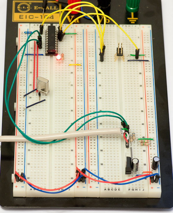
Here’s how the end result should look like:

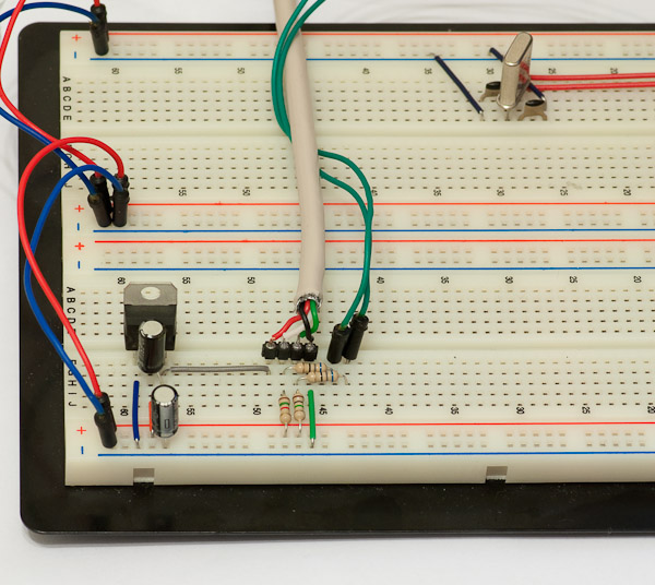
Here is another closeup of the power part and USB jumpers. Note how 5V from USB goes to regulator only and nowhere else.

By the way, if you need a refresher on how to connect the RESET pullup and 6-pin header and use the programmer, check out this excellent tutorial – wiring is the same but of course pin locations in ATtiny2313 are different than in ATtiny45. Connecting the crystal is also very easy, just connect the two legs of the crystal to PA0 and PA1, and add ceramic capacitors between each leg and ground (they need to be close to the crystal to make it stable).

Software side – preparing for V-USB

Now for the good stuff! If you did not already test that your ATtiny2313 setup is working, I suggest you to do that now. A good way to do it is to use the following simple test program:


#include 

#define F_CPU 1000000UL  // 1 MHz
#include 

int main() {
	DDRB |= 1; // LED on PB0
	
	while(1) {
		PORTB |= 1; // Turn LED on
		_delay_ms(500);
		PORTB &= ~1; // Turn LED off
		_delay_ms(500);
	}

	return 1;
}

This test program has the great additional feature that once we update the fuse bits for 12 MHz clock, it’s easy to verify that blink gets 12x faster. Now for ATtiny2313, we want to disable the internal clock/8 division and use an over 8 MHz clock with 14 clock cycles + 4.1 ms startup delay (CLKSEL=1111, SUT=10). This means that low fuse should be 0xEF, which is done using avrdude command “-U lfuse:w:0xef:m” (without quotes). In case you are using any other part or just want to check it yourself, use the excellent AVR Fuse Calculator.

Once you have updated the lfuse, reset or reprogram the chip to verify that the LED is now blinking 12 times per second. Update the blink example’s F_CPU to 12000000L and reflash to verify that the blinking returns to 1 Hz speed. Congratulations, everything is now ready for the V-USB -part of the tutorial! I will stop here for tonight, and post the third part of this tutorial shortly, covering the basic V-USB setup for our circuit.
Proceed to the next part of this tutorial

61 comments

Marek:

A very nice tutorial! I am looking forward for the third part… :-)

isik:

wow thanks this tutorial is really handy

slink:

I read the hardware condiderations over at the V-USB page. I see that they consistently use the 1k5 pullup on D- but I don’t see them using any pullup on D+. What is the advantage of your 1M resistor in this schematic?

jokkebk:

@slink
I went through several USB tutorials before making my own device, and one recommended such a resistor just to avoid current spikes generating spurious interrupts on INT0 pin of AVR. I think it was in V-USB’s example project “PowerSwitch”.

It is probably not needed and 1 M resistor won’t protect against much in any case. :)

bjw908:

Is it possible to make this work with the ATtiny45-20PU? What changes would need to be made? Any help would be greatly appreciated.

jokkebk:

@bjw908
I don’t see any problem with getting the example run on ATtiny45. If you use something else than a 12 MHz crystal you need to check that V-USB supports it.

Also, after crystal, reset, VCC and ground pins the only ones left are the three used by 6-pin programing header (SCK/MOSI/MISO lines), so you need to use them for both programming and USB lines / LED. Should not be a big problem as both USB lines and LED have series resistors. Should there be a problem with programming or USB operation, you can of course first detach USB, attach the programmer, and after flashing, detach the programmer and re-attach USB. :)

D+ needs to be connected to INT0 pin to avoid using two lines for it, so in ATtiny45 you need to have it in PB2. PB1 could probably be used for D- and PB0 for LED, or vice versa.

BreathboardLover:

Hi, thanks for your tutorial, it’s great and i learnt a lot from this pages. I have a simple question, why did you use an external oscillator instead of the internal one (as in attiny85)?

jokkebk:

I had a ATtiny2313 with 12 MHz oscillator already wired when I started playing with V-USB, so that’s the reason. :) Also, the code becomes a little more complex with ATtiny85 because of oscillator calibration, so starting without that complication seemed like a good idea.

BreadboardLover:

Ahnn ok :-)

ed:

No doubt I am missing something basic here which prevents me from grasping what is going on.
In the numbered list step 7 and 8, what is it exactly that you program into the chip? a bootloader AND a led flash program?
Anyway, then in ‘Software side’ you (re)program it again with a led flash program. Is that at that moment the only thing that is in that chip?
Anyway, then in part 3 of the tutorial you do a lot of jiggling with files and then Right above ‘WINDOWS DRIVER HELL, you maka something that makes you ‘ready to deploy the code to the chip’ Is that than actually what you do at that time? Flash the chip for a 3rd time with the actual VUSB code/bootloader/whatever.
Tnx

jokkebk:

Hi ed. Yeah, there is no bootloader in any point of the process – I actually first program a short program that just toggle’s the LED pin, and no bootloader at all, as I’m using a ISP programmer that does not need a bootloader. Same for the later steps, the flashing always replaces what was there before.

Mauro:

Hi, thanks for your tutorial it’s great.
I have a doubt and I hope you can help.
I tried to do the same circuit but with Atmega16 and i use stk600 with AVR Studio 5.1.
I difine #define F_CPU 12000000UL and the fuses Ext. RC Osc. 8.0MHz – 12MHz; Startup time: 18CK + 0ms; (CLKSEL=1000, SUT=00) is this correct?
I did it in stk600 with ext. 12Mhz Cristal and works. But if i put the microcontroller in my circuit with the cristal nothing happens, why? i tried with Two 27 pF ceramic capacitors and nothing happens, i tried to Two 15 pF ceramic capacitors and noting happens too.
But if i program the fuses with the internal oscilator works fine.
Is not supose to work with the ext 12 MHz cristal?

Thanks

jokkebk:

External RC oscillator is different than crystal. Try some of the “External crystal/resonator High freq.” options, preferably with some of the longer startup times (SUT), you might have more luck with those!

Mauro:

Thank you very much.
With “External crystal/resonator High freq” works :)

erko:

Hi, great tutorial!
You wrote: “11.Connect D+ and D- to PD3 and PD2, respectively – use 68 ohm resistors in series here!”
Shouldn’t that be: “PD2 and PD3”?

jokkebk:

Wow, you’re right! It seems I got it right two times out of three. Thanks for pointing this out, I corrected the mistake!

abd rmdn:

hi, thanks for tutoring such helpful things.
i have this problem and i hope u help me with it::
im using atmega32a .. i dont c why i have to put an external crystal isnt the internal good enough,.?!
and what config do i need to do if external crystal should be added??!
and how can i set those (CLKSEL=1111, SUT=10) is it by software??! or giving a high voltage on specific pins??!

really appreciated …
and thanks in advance..

jokkebk:

The internal oscillator is quite inaccurate, so external crystal is a lot easier method to get the accuracy required by USB communications. Also, most AVR chips can only achieve 8 MHz with internal crystal. For ATtiny45/85, the internal oscillator combined with the build in phase-locked loop (PLL) multiplier can reach 16.5, but still needs to be calibrated – see my ATtiny85 post for details.

Fuses (clock, start-up time) are set using AVRstudio programming tools or “avrdude” command-line program – here’s a good tool to calculate the necessary fuse byte values:

http://www.engbedded.com/fusecalc/

I would recommend googling around a bit to understand the fuses so you don’t make any mistakes – wrong settings may render the chip unusable (for example, you can disable further programming completely…)

abd rmdn:

i sat the fuse bits … and made the circuit ..
but still when i plug the USB in .. it gives me USB cannot be recognized…
i sat the fuse bits as follow::
ext. crystal/resonator high freq; start-up time: 16ck-4 ms
for my 12Mhz crystal… and i tried the 16MHz also..
but nothing changed….
……
dont know if im mistaking with this configuration..
but to be clear i used a 22pF capacitors instead of 27pF… can that be a big difference that effects the circuit’s purpose…

i’m really working hard to get this USB circuit working but no news ..so i hope u help like u did before … :)

jokkebk:

There’s a simple test you can use to see if the crystal and fuses are working properly: Make a simple program that blinks a LED every five seconds or so, and time if it works as it should. There’s a test program template you can modify (just change F_CPU to match your crystal speed, e.g. to 12000000).

Second, the usbconfig.h also contains a #define that tells (in kilohertz) the V-USB library which frequency your circuit is running. Make sure it’s also correct, e.g. 12000 for 12 MHz crytal, 16000 for a 16 MHz one, and so on.

Eugie Limpin:

Hello there! I’d like to follow this tutorial and I’m in the process of buying the parts I need. I noticed that there are 4 (as far as my shopping went) types of ATTiny 2313:
ATTINY2313-20PU, ATTINY2313A-PU, ATTINY2313V10PU and ATTINY2313V-10PU. The first two has 20MHz max freq while the latter two has 10MHz. Is there a particular model I should get to follow your tutorial?

Thanks!
Eugie

jokkebk:

The 20PU version capable of operating frequencies of over 10 MHz is needed to work with 12 MHz crystal used in the tutorial. :)

Eugie Limpin:

Thanks! I’ll buy that then. Wish me luck!

Veggie:

This tutorial is incredibly useful for getting into this stuff.

The one deficiency I find is that you completely gloss over the AVR Fuse Calculator. That page has many options to select from, and I’m not really sure what options to set for my particular device to accommodate the 12 MHz crystal. Which options would you suggest I pay attention to?

Thanks!

jokkebk:

A good way is to use avrdude to read the current (default) fuse settings of your device, then use the Fuse Calculator to get those same fuses, after which you change just the crystal setting or any other settings you actually understand (that’s how I usually do it :).

You might also want to check my AVRweb utility, it can read the current fuses and update settings accordingly, although it’s still in early alpha stage, so double-check with AVR Fuse Calculator if you want to be sure…

Mina:

do i need to put the pull-up resistors while using atmega32?
any btw any other changes would happen if i use atmega32?

jokkebk:

Yes, atmega32 (or atmega328?) will need the same setup. Usually only changes needed are to change the pins to corresponding ones in ATmega – if INT0 pin is something else, you’ll need to route D+ there and also update usbconfig.h accordingly.

Buraev Ravil:

Can I use microcontroller AT90S2313-10SI instead ATtiny2313 ?
Can I use quartz 16 Mhz instead 12 MHz ?

jokkebk:

You’ll need to check MCU specs that the 16 MHz frequency is supported, some xxx-10 -models only go to 10 MHz. And of course you need to update V-USB config accordingly, I vaguely recall that 16 MHz is also supported, but you may want to double-check. Otherwise it will probably work just fine. :)

adampater:

You specify ceramic capacitors to stabilise the crystal. Would tantalum work as well? That’s what I’ve used with a 16 MHz crystal and an ATTiny2313 – don’t recall why just now.

I set the fuses to “lfuse:w:0xff:m hfuse:w:0xdb:m”, intending to use the 16 MHz crystal, but the MCU the falls silent. If I shift it to a breadboard with an 8 MHz crystal it’s happy. I suspect the 16 MHz Xtl isn’t functioning correctly but don’t know how to confirm that without a CRO, apart from swapping out the xtl and caps.

With a good 5.05 Volts, shouldn’t it all “just work”?

jokkebk:

I’ve never seen tantalum caps in picofarad range, only nF. If you have too big caps, the high frequency crystal probably fails to reach stable oscillation. It could also be just the crystal, I’ve heard they are rather fragile. And some crystals might just be plain picky about the capacitor value (I’ve personally used 18-27 pF ones without issues, as long as both are the same).

jokkebk:

Oh and 5.05V sounds just fine. Of course if there are big swings, it might be an issue, but that’s rare (I once plugged an AC adapter to a DC regulator circuit, no wonder why the projects worked oddly :D)

Hausy:

hy,
Can u please help and tell about programming attiny2313. What programmer did u use and what about boot loader?
Some coments or good tutorial would be great.
Do u programm microcontroller and then add it to circuit, or u are programming it in cicrcuit?
Actually i’m new in this and i didn’t get it.

jokkebk:

Hi. I suggest you go through some of the simpler tutorials on AVR Freaks forum’s tutorial section, or maybe this one I also linked in the post: http://imakeprojects.com/Projects/avr-tutorial/

I personally use USBtiny programmer from Adafruit, but have occasionally used an Arduino, too (there’s a tutorial about it in my blog, too). It’s often quite easy to leave the pins required to program the MCU free, so I can program the chip in circuit, not outside of it (also saves a ton of time when you need 20+ attempts to get the program to work properly…).

Hassan:

Hi
I’ve a question from D+ line and Pull up D+ with 1M res.
in vusb\circuits\ D+ pulled down with 1M res.
ty

jokkebk:

The circuit is adapted from V-USB PowerSwitch reference project, which has a pullup. I think (but not certain) the pullup/down is used to indicate desired communication speed or something. Anyways, it has worked fine with pullup. :)

Hassan:

thank u
in your main() you used usbDeviceDisconnect() and usbDeviceConnect()
but in usbconfig.h in your project you didnt define USB_CFG_PULLUP_IOPORTNAME and USB_CFG_PULLUP_BIT
in vusb comments tells:

/* #define USB_CFG_PULLUP_IOPORTNAME D */
/* If you connect the 1.5k pullup resistor from D- to a port pin instead of
* V+, you can connect and disconnect the device from firmware by calling
* the macros usbDeviceConnect() and usbDeviceDisconnect() (see usbdrv.h).
* This constant defines the port on which the pullup resistor is connected.
*/
/* #define USB_CFG_PULLUP_BIT 4 */
/* This constant defines the bit number in USB_CFG_PULLUP_IOPORT (defined
* above) where the 1.5k pullup resistor is connected. See description
* above for details.
*/

and u just connect D- to Vcc with res and didnt connect to any pins of MCU then i think usbDeviceDisconnect() and usbDeviceConnect() dont work.
is it correct?

Hassan:

My second question is not relevancy to first question

my purpose from this sentence is connect D- to a pins of MCU to pulling up and pulling down D- for connect and disconnect USB device

sorry i cant type and speak English very well.

jokkebk:

Yeah, exactly as you said, I went for the simplest option without support for connect/disconnect. You can probably implement that by uncommenting the lines and configuring them for the port pin you’ve chosen to use for connect/disconnect.

jokkebk:

No problem, your writing is perfectly understandable. :)

Rahul:

Can I use this to burn firmware in atmega8?

Joonas Pihlajamaa:

The pins will be a bit different, but there are no big differences between the tiny and mega platforms, so I’d wager yes.

Ashok:

Dear Joonas,

Firstly, Hats off, hats off to your excellent tutorial. I tried all the steps until programming the fuses successfully. But there was a problem at a point.

I am using

Atmega32A MCU,
16mhz clock
22pf capacitors
USBASP programmer

I tried to disable my programmer to power the target board by simply not connecting the power from my usbasp programmer and rather connected the power from the usb connector. When you meant to disable the power to the target from the programmer I assume it should ideally be a jumper setting in the programmer to do that right? Unfortunately my programmer does not have anything like that. Hence I decided not to connect it at all from my programmer. Now when I try programming my device with the power derived from the usb cable but not from the programmer it is inconsistent. The errors I see are,

* target doesn’t answer
* target answers but problem reading either of the fuses (hfuse or lfuse)
* sometimes it works fine.

Hence the state is not stable.

Do you have any ideas on how to go about this problem?

Regards,

Ashok
http://www.hashok.com

Joonas Pihlajamaa:

Thanks! In case you cannot disable power from programmer, just leave the USB power off – the programmer data signals are likely relative to it’s ground, and without common ground it’s likely to not work very well. You could even have the MCU completely removed from the project while programming (although that shouldn’t be necessary).

Theoretically you could just connect programmer ground but not VCC, but in that case you’d need to be sure that the grounds of your device and programmer are exactly the same (e.g. same USB hub), otherwise you can get nasty ground loops.

Joonas Pihlajamaa:

And with “USB power off” I mean disconnected while you program, and then disconnect the programmer when you rewire the USB power back…

Ashok:

Thanks for the quick reply mate! Will sure try what you have advised. BTW, when you meant “same USB hub” did you mean using an external usb (multi usb ports extension) hub connected at a single point the pc?

Ashok:

Forgot to tell you that meanwhile to handle this power/mcu randomized detection problem I flashed the MCU separately with the avr code and went on to the next of “Windows driver hell” step. It is true and as you said its really a hell for that step has not yet been sorted out for me. Hence thought of downloading your projects files and flash it first to see if the USB gets detected and the driver installed.

Joonas Pihlajamaa:

“Same USB hub” essentially meant any two ports that share a common ground. Adjacent USB ports in a computer, monitor, or USB hub all apply. :)

However, for example my monitor has a separate power supply and it’s ground is usually >0.1V different from PC. Probably nothing to worry about, but I’m still hesitant to use it (i.e. connect a device to monitor and use my USB scope connected to PC, for example). :)

jonny:

Nice Tutorial.
you have a very minor typo in the article: “Breaidboard setup”

Joonas Pihlajamaa:

Haha, thanks I’ll fix that. :)

carlos:

Hi: I decided to use an attiny84, for lower size. But I have several troubles calculating the fuses for v-usb.
Whats the trick?

http://www.atmel.com/Images/doc8006.pdf attiny84

Joonas Pihlajamaa:

Easiest way is to use the AVR Fuse Calculator, or alternatively my AVRWeb GUI to flash (you first need to “Detect MCU” with avrweb and then go to fuse setup). The main things to change are disabling the 1/8 clock scale, and setting clock for 12 MHz crystal, I’d think the settings are very similar to ones described in the post, only the actual fuse value will be different.

TheLeon:

Hello.
(I’m sorry, I don’t know english very well). I’m beginner. I’d flash Attiny2313-pu10. I bought USBasp v2.0. JP1 was connected to 3.3v. JP3 was connected to Slow SCK.(I read it another site).

But when I flash the chip Avrdude_prog_3.3 software shows me these texts:

avrdude.exe -p t2313 -c usbasp -P usb -U calibration:r:calibration.hex:r

avrdude.exe: warning: cannot set sck period. please check for usbasp firmware update.
avrdude.exe: error: programm enable: target doesn’t answer. 1
avrdude.exe: initialization failed, rc=-1
Double check connections and try again, or use -F to override
this check.

avrdude.exe done. Thank you.

Can you help me?

Trey:

Hi,

could one use level shifters instead of the zener diodes? For example: http://husstechlabs.com/wp-content/uploads/2010/09/Level-shifter.jpg
uses a 2n7000 mosfet and two 10k pull-up resistors.

thanks!

peter:

Hi !
I Have a question about the crystal. Is it possible to run this USB on 14.7465MHz or something like that ?

P0rtbo:

I have tried this with an Atmega8-16PU. It seemed to be unstable at 3.3 volts, so I had to use 5 volts, and 3.6 v zener diodes for D+ and D- as suggested, and it works with this setup.
Instead of the V-USB I used USBtiny, that works too.
Thanks for the great tutorial!

StephaneAG:

Hi !

Just passing by, as currently diggin’ through every possible “clean” V-USB tutorials ( starting by yours ;p )

=> if I’m not wrong, the two polarized caps of 10 uF ( C3 & C4 ) have to be flipped over for the circuit to be correct ( as shown in the schematic in the part 1, the negative side has to be connected to Gnd )

( just posting in case it troubles some newcomers to electronics )

feel free to correct me if I’m making a mistake,
and thank you for such great tuts’ :)

+

[ now onto part 3 .. ;p ]

Joonas Pihlajamaa:

Whoops, thank you for noticing this! My intuition seems to have been that negative terminal is straight like the minus sign (and I think I looked it up at some point, obviously wrong :). I’ll fix that ASAP (i.e. when I am both home and remember this…)

Daniel:

I was just reading your tutorial and wanted to mention that the assertion that you’ll need 4.5V for anything above 10MHz is not quite correct (e.g. for the ATTiny85). While it says at the beginning of the data sheet “ATtiny25/45/85: 0 – 10 MHz @ 2.7 – 5.5V, 0 – 20 MHz @ 4.5 – 5.5V” there’s also a more detailed graph in section 21.3 which specifies a linear increase in speed (“safe operating area”) with increased voltage between 10 and 20MHz. If you do the math then you should arrive at 3.204V being in the safe operating area for 12.8MHz.

Mccoring:

can i make it on atmega8? if yes, do i need a programmer?

Rasheed:

If D+ and D- lines require 3.3V, then why do we use 3.6V 0.25W or 0.5W Zener Diodes on these lines?