Code and Life

Programming, electronics and other cool tech stuff

Supported by

Supported by Picotech

V-USB with ATtiny45 / ATtiny85 without a crystal

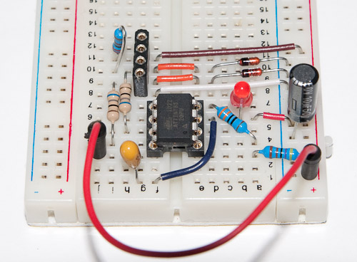
One guy at Hack a Day remarked on the long wire runs in my V-USB tutorial breadboard setup. So I thought I’d build upon the part 4 of the tutorial but modify the setup a bit to run the AVR at 5 volts and use zener diodes to drop D+/D- voltage, thus eliminating the need for a regulator. And why not stop there. ATtiny45 and ATtiny85 are smaller than ATtiny2313 and have an internal oscillator that can be calibrated to provide 16.5 MHz clock, accurate enough for V-USB to do its magic. I challenge anyone to drastically shorten these wire runs!

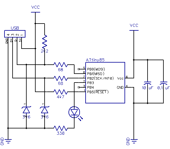
In the photo, I used a 4-pin header to show the place of the USB cable so the zener diodes would not get obstructed. Note that due to the angle it can seem like the 0.1 uF tantalum cap (light brown one) is wired to PB4 when it really is going to GND pin! Here’s the schematic, heavily borrowed from V-USB’s EasyLogger reference implementation:

Note: 2.2 kohm pullup for D- was missing in the schematic, it has now been corrected.

Main code changes needed are the change of pins to PORTB. Also, the oscillator calibration routine needs a hook added to the config. Here are the changes I made to usbconfig.h:


#define USB_CFG_IOPORTNAME      B
#define USB_CFG_DMINUS_BIT      1
#define USB_CFG_DPLUS_BIT       2
#define USB_CFG_CLOCK_KHZ       (F_CPU/1000)
#define USB_CFG_HAVE_MEASURE_FRAME_LENGTH   1

// The following needs to be uncommented
#define USB_RESET_HOOK(resetStarts)     if(!resetStarts){hadUsbReset();}

// Add the following after USB_RESET_HOOK
#ifndef __ASSEMBLER__
extern void hadUsbReset(void); // define the function for usbdrv.c
#endif

Note that USB_CFG_CLOCK_KHZ now relies on F_CPU constant. Furthermore, F_CPU can be set in the Makefile by passing -DF_CPU=16500000 as a command-line argument to gcc, so defining it can also be omitted from main.c. Another thing we need to change in the makefile is to set mcu/part code to attiny85 for both avrdude and gcc.

In main.c, we only need to remove definition of F_CPU, change the LED pin from PB0 to PB3, and add the calibration routine. The calibration routine in EasyLogger has a slightly mind-bending binary search which, while short, does not take into account that ATtiny45 and ATtiny85 have OSCCAL which works in two overlapping frequency regions, 0..127 and 128..255. So I made my own which is as short but does search the two spaces separately for the optimum value (on the other hand, my routine does not descend to 0 or 128, which should not be an issue).


#define abs(x) ((x) > 0 ? (x) : (-x))

// Called by V-USB after device reset
void hadUsbReset() {
    int frameLength, targetLength = (unsigned)(1499 * (double)F_CPU / 10.5e6 + 0.5);
    int bestDeviation = 9999;
    uchar trialCal, bestCal, step, region;

    // do a binary search in regions 0-127 and 128-255 to get optimum OSCCAL
    for(region = 0; region <= 1; region++) {
        frameLength = 0;
        trialCal = (region == 0) ? 0 : 128;
        
        for(step = 64; step > 0; step >>= 1) { 
            if(frameLength < targetLength) // true for initial iteration
                trialCal += step; // frequency too low
            else
                trialCal -= step; // frequency too high
                
            OSCCAL = trialCal;
            frameLength = usbMeasureFrameLength();
            
            if(abs(frameLength-targetLength) < bestDeviation) {
                bestCal = trialCal; // new optimum found
                bestDeviation = abs(frameLength -targetLength);
            }
        }
    }

    OSCCAL = bestCal;
}

That’s it. Again, the full main.c and usbconfig.h along with modified makefile, updated schematic and rest of the needed stuff (driver, libusb, usbdrv folders) are available as one zip file released under GPL. Interface to the new device is unchanged, “usbtest on”, “usbtest out” etc. should work from command-line like they did with the ATtiny2313-powered device.

Fuse bits

Oh and one last thing – the fuse bits need of course be changed. Remove the 8x clock divider and switch to High Frequency PLL clock (CKSEL=0001) with slowly rising power (SUT=10). For ATtiny45/85 this should result in low fuse byte of 0xE1. You might also consider 2.7 V brown-out detection, making the high byte 0xDD:

avrdude -c usbtiny -p attiny85 -U lfuse:w:0xe1:m -U hfuse:w:0xdd:m
111 comments

chris:

2,2k pull-up on D- is missing in schematic.

jokkebk:

@chris
Wow you are right, I’ll add it this evening when I get back home!

chris:

happens… anyhow – thanks for the tutorials!
my tiny is now safely hidden inside a haunted usb-cable’s ferrite core casing…waiting for april’s 1st.
Do You think with a tiny45 running w/o crystal like this an implementation of a TWI/i²c – Master/slave may be doable without the need of an HVSP like with the I2C-Tiny-USB-project?!?

Alejandro:

Dumb question but, in case you lose it, is there any possibility of a recovery? XD

jokkebk:

@chris

Thanks! I don’t know much about TWI but definitely the I2C-USB protocol bridge could be developed, I tinkered with I2C recently and accurate timings don’t seem to be an issue at all with it.

@Alejandro

I assume you are referring to my USB password generator hack? Fun one, unless you save the password somewhere, it’s not recoverable if you lose the USB stick. :) If the electronics fail, however, one might be able to attach a programmer to the Tiny45/85 chip and read EEPROM contents to recover the password.

Ken:

Hey :)

First off: Thanks for some good reading.

I’m having a problem when using this.

This is what i do:
download zip file usb_tiny85_20120222.zip, unpack, make, make flash
and then im getting errors with lfuse, hfuse and efuse. It doesnt matter wether i write lfuse 0xe1 before or after “make flash”.

to program lfuse: avrude -c usbtiny -p t85 -U lfuse:w:0xe1:m

To see what make flash outputs: http://pastebin.com/McRRF8fZ

Ken:

Hey again.

Got it working. I’ve misplaced 2k2 pull-up resistor.

Then i used: avrude -c usbtiny -p t85 -U lfuse:w:0xe1:m -U hfuse:w:0xdd:m
and then: make flash

and it works :)

Thanks again ! -Time to play around

jokkebk:

@Ken: Nice to hear you found the problem! I was just about to post that I don’t really have an idea what might be wrong, I had never encountered any similar but some kind of problem with programmer communication would’ve been my first guess. :)

Have fun with the project!

Tim:

Hello,

Thanks for the great work and sorry for my bad english,

I build the V-USB with ATtiny45 / ATtiny85 without a crystal and my problem is:
the board is a unknown device on Win XP and I do not get the program on the tiny85.
The project inf file has not effect or the libusb same.
AVR Studio and avrdude don’t find the board.
sorry for the stupid question but this is for me unknown territory

thanks Tim

jokkebk:

Sounds like some kind of hardware problem; I think the zener connections have caused most of the problems to people here, check that they are connected the right way and voltage rises to at least 3V in D- line with the pullup. Does Windows at least play the “device found” sound when connecting it in?

One way to check if it’s a driver issue is to flash the USB password generator or mouse firmware on it – that doesn’t require separate drivers so it should be recognized by Windows automatically.

That’s all I can think of at this point. And the ATtiny85 problem also sounds strange – did you change the part name in Makefile (so you’re not using “-p attiny45” or anything there)? If everything else is the same but another chip doesn’t work, it could also be some kind of power problem!

mad66:

Hi all i don’t know anything about avr programming or for that matter any programming, but i know the
Attiny 85 can be programmed in the arduino ide.Is it possible to convert the code bits of software to the
Arduino language.thanks newbie .

jokkebk:

You can program ATtiny85 in two ways with Arduino:

1) Use the Arduino IDE to upload a “AVR programmer” sketch to your Arduino (ArduinoISP) as explained in my other blog post. The code executed by ATtiny85 needs to be compiled using other tools than Arduino IDE, such as the WinAVR software stack – Arduino only acts as a programming device, and you don’t code in the “Arduino language” (which is actually C++ with extra libraries)

2) If you have a ATtiny85 already programmed with an Arduino bootloader (method 1 could be used to do it), you can then (I believe) program it much like you would an Arduino, using the Arduino IDE to upload compiled code to the ATtiny85 etc. I don’t know much of this.

Both of the above are quite complex things if you haven’t coded much before. I recommend you first spend some time programming the Arduino, and then maybe try to finish this tutorial (still quite challenging if you want to use WinAVR and Arduino instead of AVR Studio and AvrISP mk II, as I have done):

http://imakeprojects.com/Projects/avr-tutorial/

I’m thinking of writing a somewhat similar “basic tutorial” myself at some point in the future, so stay tuned.

mad66:

Thankyou that helps me in the direction i need to research ,great project look toward to more.

Charles:

Is anyone there who can lead me through this project?
I need a parts list for a start and then the SW environment is greek to me.
Email me at august04@frontier.com.

jokkebk:

Cannot help you with the project implementation and SW, but parts list can be easily deduced from the picture and schematic:

ATtiny45 (or ATtiny85)
two 68 ohm resistors, one 2k2, one 4k7
two 3.6V zeners
a LED
10 uF plus 1 uF caps (electrolytic and tantalum used in mine)

The thing usually work even without the 4k7 resistor and the caps.

TiredJuan:

Would this work with an Attiny84? I was thinking of using one to make an snes controller into USB.

jokkebk:

Based on peek to datasheets, 84 does not have the PLL (phase locked loop) unit that could be used to multiply the 8 MHz oscillator to get higher clock speeds. So while ATtiny84 will work, you’ll need an external crystal (e.g. 12 MHz) with it.

TiredJuan:

Good to hear, thanks. I think I could do it with an ’85, but I wanted an extra button for programming.

tikiman:

The V-USB firmware works fine if i plug in the device after my PC has finished booting.
I tried it with an ATtiny85 and the hounted USB cable, which worked nearly out of box.
But i couldn’t get it working when it stays plugged in while i boot or reboot the PC.
Did anyone find a way to modify the code for an HID-Device so that it can stay plugged in and is recogniced from the host after booting has been done?

Ralph:

> Did anyone find a way to modify the code for an HID-Device so that it can stay plugged in and is recogniced from the host after booting has been done?

Hi tikiman, I had the same issue, but I am a lousy programmer and so I fiddled around for a wile without really knowing what i’m doing.

But I wasn’t sucessful. I gave up and deleted the osccal stuff and used a 12 MHz quartz. The quartz version works reliable, but you have to “sacrifice” two I/O pins.

jokkebk:

Hmm, I’m wondering if the problem lies with the fact that when the PC is booted up, the device gets power but the USB communication doesn’t start until OS is ready, thus making it impossible to measure USB frame length (basis for oscillator calibration).

If that’s the case, it might work if correct OSCCAL value is stored to EEPROM, and if the device could somehow delay the USB reset until OS has started (maybe usbInit() returns success code?)

freespace:

Great article. Got my attiny85 talking via USB in no time :)

ROHIT:

MAD,
AM USING PROGRAMMERS NOTEPAD TO COMPILE THE ZIP FILE,BUT M GETTING ERRORS LIKE
main.c:9:16: error: io.h: No such file or directory
main.c: In function ‘hardwareInit’:
main.c:105: error: ‘PORTD’ undeclared (first use in this function)
main.c:105: error: (Each undeclared identifier is reported only once
main.c:105: error: for each function it appears in.)
main.c:108: warning: cast to pointer from integer of different size
main.c:114: warning: implicit declaration of function ‘__delay_cycles’
main.c: At top level:
main.c:120: error: expected ‘=’, ‘,’, ‘;’, ‘asm’ or ‘__attribute__’ before ‘main’
make.exe: *** [main.o] Error 1

> Process Exit Code: 2
> Time Taken: 00:02
COULD U HELP INTHESE

jokkebk:

Based on the errors you are getting (missing io.h) I get the feeling that your avr-gcc compiler is not installed properly, or you are trying to use normal PC version of gcc to compile the code. I would recommend googling around for a simple AVR tutorial and once you get something compiled and flashed to the chip, you can continue here.

Mia:

The device driver has been successfully installed but still windows does not recognize my device. I used atmega32, accordingly I made changes in the hardware and for the level conversion to 3.3V, I used solution B (i.e. using zener diodes) of the site you mentioned http://vusb.wikidot.com/hardware . I am stuck here in the device recognition part. Could you point me out the possible things that could have caused this problem?

jokkebk:

The most common issues are probably too long wires, too heavy (1W and above) zeners that don’t “turn on” due to small amount of current, and the USB connector should also be checked for cold solder joints.

Also, unless ATmega32 has a very similar oscillator that can be calibrated with high accuracy to 16.5 MHz, you’ll need an external crystal (and modify the usbconfig.h clock rate setting accordingly, and remove the calibration code). If you want to play it safe, start with my V-USB tutorial that does everything with an external crystal, and then when you get that working, see if you can do it with internal oscillator. That way you can tackle the external hardware and oscillator problems one at a time.

Sergio:

Thanks for the tutorial. I really want to make a similar project and I will follow your tutorial.

However, I have a doubt related with the diodes. I’m struggling to find a 3.6V 500mW diode locally so I’ll buy them online.

At http://vusb.wikidot.com/hardware they said that for solutio B a diode similar to 1N4148 so I bought some of them to later realize that they are marked as “High speed diode” not zener diode. Furthermore, I can’t find if they are 3.6V o another voltage.

Is this component I’m looking for? If not, where can I buy 3.6 500mW diode?

Thank you.

jokkebk:

You should be able to get small 3V6 zener diodes from almost every online electronics supplier, including Digikey and Mouser. Even 1/8W (125 mW) should do just fine.

Normal diodes can be used to drop the voltage, they usually drop about 0.7-0.9V, but the current only goes to one direction, so it’s mainly suitable for scaling down 5V from USB VCC to 3.2-3.6 volts (by puting two diodes in series), so you can power the AVR from that and don’t need to drop voltage for USB data (if the AVR chip is powered from ~3.3V source, it’s data pins will also be the same, so no need for zeners).

“High speed” in diode refers to the speed which they need to turn on / off. It means that the 1N4148 is also suitable for signalling applications where current goes on/off fast – for power uses, there’s no harm in that (but little benefit either). You cannot use diodes to drop D+/D- voltage, because the diodes only work one way, and I think USB data lines are bi-directional.

Sergio:

Thanks for your answer.

I finally got 10 3.6V 400 mW diodes. However, I have a problem now :/

I built a test circuit similar to the one in your post. However, I attached the zener diode to the 5V line to be able to test the resulting voltage.

Unfortunately, no voltage regulation is performed. However, If I replace the diode with a 3.6V 1W one, the signals regulates to 3.3V as expected.

Any idea?

jokkebk:

Hmm, you may need to check the datasheet to see what kind of current is needed for your 3.6V zeners to start conducting – when I was looking into “zener voltage regulation” I saw a couple of good tutorials that showed how the current calculations are done.

And remember that the zeners need to be connected “backwards” for the regulation to work. And in any case, the voltage does depend on the current somewhat.

Oh and if the 1W zeners work nicely, just use those. :)

Sergio:

Thanks for your answer. I’ll check the minimum current to make it conduct.

Yes, I’m connecting it backwards.

I read somewhere that 1W won’t work because they generate to have capacitante (?) for the USB speed.

jokkebk:

Yes some people have reported that they couldn’t get it work with 1W zeners, I don’t know the reason. But if you’re doing it on a breadboard, probably it doesn’t hurt to try… (other than the 1 % chance that you burn your USB port – most do stand 5V very well though)

Sergio:

I was thinking, I testing connecting

5V—-68 ohm —–a– zener diode –b– round

and measuring between “a” and “b”.

It is possible that the diode doesn’t conduct in this configuration but it will work if connected to D+ / D-.

Thank you.

C Brosseau:

OK. It tooks me 10 hours to make this work. Here, I was just able to get 3.6 V, 1 Watt zener diodes. I’ve never been able to make it work. Then I found 3.2 V, 1/4 Watt zener diodes. Didn’t work. After many many attemps, I’ve begun to use a scope to have an idea of what was going on… and it worked! It was due to the scope impedance. So, I’ve added a 500 k resistance between ground and D-. And it works!!

Also, I power the uC from USB. I need to put a 0.1 uF in parallel to Vcc and Gnd.

jokkebk:

Great to hear, congratulations! Sounds like it really took some perseverance, so I recommend you to uncork one of your favorite beverages to celebrate. :)

Csoasu:

Hello,

thanks for your tutorial. I got it working in a breadboard perfectly.

However, I’m trying to get it done in a stripeboard and it’s not working.

Would you mind to take a look at my design? Supposing the wiring is done properly, is this design equivalent? I’m specially concerned with the D+, D- part.

Ignore the button for now :)

Here a pic of the design:

https://www.dropbox.com/s/s6y2ekoee9080jo/20121219_222135.jpg

Thank you very much.

jokkebk:

Sorry, took a bit long. The design does look quite the same, assuming you have horizontal connected strips on backside, and have soldered everything there. I wonder how have you achieved the connector to such a board, usually all lines (D+, D-, GND, VCC) are in the same horizontal row?

For debugging, I’d first check VCC and GND lines for voltages, and make sure they reach the MCU. If you have an oscilloscope, you could also monitor the power lines for possible glitches. If there’s anything wrong with GND (bad connection, connected to USB connector shell instead of pin might make a difference, too), zeners and such might not work properly. Next would be to see if the zeners drop the voltage to 3-3.7V, and checking that the button does not hamper functionality in any way.

Other than that, I cannot offer much more than the best of luck! :)

Neal:

I finally have the V-USB working with an ATTiny85. Now I want to add some of my own functionality to the code. Now I want to debug my added code.

How can I force a USB reset to occur without disconnecting the 5v of the USB connector? I need to keep the 5v connected so my hardware debugger (Dragon) doesn’t go haywire.

jokkebk:

In the device side, the code marked with “// enforce re-enumeration” should cause a USB reset, so you make your project to respond to some signal (like USB control message, hardware button) and run that same piece of code, it might very well work.

If manual reset without shutting power is enough, you could just wire a button to RESET pin of the ATtiny.

USB reset from PC side may be harder. Even if you can force re-enumeration there, I’m not sure if V-USB handles that cleanly – if it doesn’t, you’d need to signal to the MCU to reset itself somehow.

Neal:

Thank you for the reply. Since I have been able to reset and debug using the Attiny2313 USB circuit you have in your tutorial, I believe the problem has to do with an improper oscillator cal when I am in debug mode. BTW my debugger (Dragon) uses the reset line for debugwire mode. The debugger might be changing the timing somewhat during the cal routine.

Maybe if I knew what value that OSCCAL came up with I could use it in debug mode and skip the calibration routine.

Do you what value is typical for OSCCAL that I might try?

Thanks
Neal

oliver:

obdev says that you shouldn’t use 2k2 but instead use 1k5 as a pull-up resistor, yet this somewhat newer design still uses 2k2. Why is that?

http://forums.obdev.at/viewtopic.php?f=8&t=2376&sid=61e17584b18976b195109dd971ff32fa

bryce:

How would you keep the led off for 5min and then turn it back on?

jokkebk:

If it’s “about 5 min”, you could just increment some counter (you may need two levels of counters, as 16-bit counter may not be enough) in the main loop and figure out what value is reached after about 5 minutes.

If you need accurate time, AVR timers are a good choice, there are nice timer tutorials in AVRfreaks tutorial forum, for example.

george:

I just noticed that the schematic.png in the zip file is the old one without the 2.2 kOhm resistor. It may confuse someone.

Kapil Saraswat:

Can I use reset pin as output?

jokkebk:

I actually don’t know. Only thing I do know is that using reset pin has some special considerations and may make it harder to reprogram the chip. The ATtiny45/85 datasheet has all the info, and you can probably find out more through googling or forums, too.

Simon:

Wouldn’t it be possible to use the ATtiny2313 without an external crystal as well?

jokkebk:

I vaguely recall that ATtiny2313 couldn’t get to 12.5 MHz without external crystal, more like 8 MHz. Or then the internal oscillator was not accurate enough in that model. In any case, I’ve understood that it’s not possible with ATtiny2313.

Resistor:

Keep on working, great job!

jokkebk:

Fixed in here too, now. :)

jokkebk:

Never attribute to knowledge that which is adequately explained by ignorance. :D

It means that I’ve taken the 2k2 value from some old V-USB example projects, and they’ve likely changed their recommendation later on, and I’ve failed to notice. 2k2 has worked well for me though, I doubt there is a big difference. At least in the forum post you referred, someone (you?-) seemed to have calculated the math and both result in similar levels of current.

jokkebk:

If you get the calibration to work once, you can just save the value in EEPROM and then disable calibration from firmware and get it from EEPROM instead, thus making it possible to debug. Unfortunately I’ve never outputted the value (though it would be quite easy only to modify my USB HID keyboard tutorial to send the value as keystrokes)

Erwin:

Cool project! Can the Tantalum cap be replaced with a normal one?

jokkebk:

Sure. The basic idea is to have a 10 uF cap in the power rails to help the power supply, and 1 uF right next to MCU VCC and GND to help level voltage drops when MCU needs momentarily more current.

With a small breadboard of course the two caps are quite close to each other so just one 10 uF would probably work, too.

nick:

Hello, I’m trying to change the USB pins to 3 and 4. Those are the changes I made:

# define USB_CFG_DMINUS_BIT 3
# define USB_CFG_DPLUS_BIT 4

I can’t get the device to enumerate. The circuit I’m using is correct, I have tested it. What else should I check? I don’t think D- needs to be on the INT pin. Does it?

jokkebk:

I think only D+ needs to be in INT0 pin of the MCU (otherwise you need to customize V-USB with usbconfig.h). If you had it working with another pin configuration, one way would be to revert to the working configuration and start changing pins one by one, so you’ll see where it goes wrong. Theoretically it could also be that some pin is fried (I’ve burned a couple I believe), but more usual is that some function (like reset, SPI, etc.) is interfering (for example if you have a programmer connected to SPI pins).

nick:

I’m using the micronucleus bootloader with pins 3 and 4. I can upload programs using it correctly. The USB circuitry works, but I’m having problems with the program posted here. I did a diff on the two usbconfig.h files but everything is identical.

I also uploaded the program using an ISP programmer, just in case the bootloader interferes but nothing changed. I’m puzzled!

jokkebk:

I have to admit I’m stumped, too. :) Seems like you’ve done everything quite carefully so it should work. I’ll need to build this myself one day soon again and see if I can get it working myself.

By the way, if you have D+ in either PB3 or PB4, neither has INT0 – I think V-USB by default relies on D+ being in INT0 pin, which is PB2 (physical pin 7) – if you move it elsewhere, it won’t work without additional configuration.

nick:

Yes, you are right. I missed a block of code that was not were it was supposed to be (at the end of the file). This is was micronucleus is using to setup the interrupts. You’ll need to add it on the bottom of the usbconfig.h file of this project.


#define USB_INTR_CFG PCMSK
#define USB_INTR_CFG_SET (1 << USB_CFG_DPLUS_BIT)
#define USB_INTR_CFG_CLR 0
#define USB_INTR_ENABLE GIMSK
#define USB_INTR_ENABLE_BIT PCIE
#define USB_INTR_PENDING GIFR
#define USB_INTR_PENDING_BIT PCIF
#define USB_INTR_VECTOR PCINT0_vect

I got it working!

jokkebk:

Great to hear, thanks for the update. :)

epsilonjon:

Hi, just wondering why you use 3.6V zeners instead of 3.3V zeners? Also how do you know to use a 2.2k pull-up resistor to the 5V supply? Should we not be pulling up to 3.3V to indicate speed, as per the USB spec?

Thanks!

Lewis Balentine:

” I challenge anyone to drastically shorten these wire runs!”

Why on earth did you waste all that valuable copper ?
I need to attach a .png file.

Joonas Pihlajamaa:

Haha. :D I got your .png, thanks, maybe I’ll do a short post to show I was one-upped. :)

Andi:

THANK YOU!

Saving in the EEPROM works out of the box and every time I try!

David Halterman:

Thanks for the tutorial, great job.

I wired this up and first time was able to get LED to light up. After that nothing. I know get 0v on pins 2 and 3. (Assume fried the diodes???).

I found the USB input was 7.55-7.65 from USB Port 2.0 (I don’t have a 1.x USB port). It seems this would be a common problem with more recent systems and giving this to a user to plug in…no telling what port they will plug it into (or how they would know difference).

Question: Should this work with 7.x volts, if not, should design go back to using the regulator since a user could plug this into USB 3.0/2.0?

Thanks for your reply.

Joonas Pihlajamaa:

Hi! Sounds really strange, all USB versions should have about 5-5.2 volts between VCC and GND pins – I’m using USB 2.0 ports myself as they are everywhere – the 1.x just refers to the speed as USB 2.0 is compatible with that, electrical characteristics should be the same.

If you really have such a high voltage in USB port, regulator might be a better option. I don’t know if you can easily fry zener diodes, but it may be possible to fry the ATtiny (especially if you have some connection backwards) or maybe even the USB port (though you can easily check that with another USB device in that port).

David Halterman:

OK, forget my previous post. I tried this on several other computers and got same results. I finally tested volt meter on 1.5v battery – it read 2.05. Used a different volt meter and USB not shows 5.02+-.

I redid the board and still won’t work. The zener diodes voltage:

D- 2.41V
D+ 4.5V

pin 4 to 1 5.01V

Any thoughts would be appreciated!

David Halterman:

BTW, zeners are Vishay 3.6V 0.5W 2%. PN TZX3V6C-TR

Joonas Pihlajamaa:

I don’t have one built currently so I cannot say about the zener voltages, but other than double-checking every connection, if you have a regulator you might try powering everything with 3.3V, skip the zeners and see if it works that way. Also, you can start with just checking if you can get the MCU blink a LED, next calibrate the clock and maybe use a frequency counter or scope to strobe a pin and see if the frequency is close enough to 16.5 MHz.

Moe:

Great example. Quick question: Is there anything keeping me from running D- and D+ on PB0 and PB1, as in:

#define USB_CFG_DMINUS_BIT 0
#define USB_CFG_DPLUS_BIT 1

Or are there special functions on the pins you used that restricts D- and D+ to use those pins?

Joonas Pihlajamaa:

Thanks. Flashing might be harder as PB0/1 are used for that, too, and you need to make sure the circuit will not compete with the programmer when you connect the ISP, and zeners etc. won’t hamper the programmer functionality. There is an application note on those requirements, you might want to check that out.

Also, D+ needs to be in interrupt pin, and V-USB configured for the correct interrupt. Current setup has D+ in INT0. There seems to be PCINT0 and PCINT1 in PB0/1 so it may be possible to configure V-USB to use those.

Joonas Pihlajamaa:

http://www.atmel.fi/Images/doc0943.pdf was the application note. From a quick glance, basically the ATtiny should never attempt to drive PB0/PB1 when RESET is held low. If the programmer is designed smartly to start pulling reset low, and you don’t have anything to delay the reset line in your circuit, the AVR should do this automatically, so you only need to unconnect USB to make sure PC doesn’t contend these lines. Also, with any luck, the zeners limiting the voltage will not do extra harm (even at 5V the AVR probably sees 3.3V as logic one), but you may need to think that one out to be sure.

Dimitris Zervas:

when I connect it to the USB port, I get errors in dmesg:

[ 6625.447376] usb 4-1.1.2: new low-speed USB device number 76 using ehci-pci
[ 6625.513852] usb 4-1.1.2: device descriptor read/64, error -32
[ 6625.683704] usb 4-1.1.2: device descriptor read/64, error -32
[ 6625.853511] usb 4-1.1.2: new low-speed USB device number 77 using ehci-pci
[ 6625.920267] usb 4-1.1.2: device descriptor read/64, error -32
[ 6626.089934] usb 4-1.1.2: device descriptor read/64, error -32
[ 6626.259829] usb 4-1.1.2: new low-speed USB device number 78 using ehci-pci
[ 6626.665913] usb 4-1.1.2: device not accepting address 78, error -32
[ 6626.732710] usb 4-1.1.2: new low-speed USB device number 79 using ehci-pci
[ 6627.138738] usb 4-1.1.2: device not accepting address 79, error -32
[ 6627.138903] hub 4-1.1:1.0: unable to enumerate USB device on port 2

Instead of a USB wire, I use a port of a usb hub that I’ve soldered wires.
I the picture with the bradboard, I’ve marked the D+ components/pins with green and the D- ones with white.
I think you can ignore the shift registers safely (used to as input.)
Also the second shift register (left one) is disconnected on purpose.
I’ve tried with and without the 4k7 resistor on reset pin.
I’ve also tried with and without a cap (10μF).

My fuses are: H: FF, E: DD, L: E1
Here is my code and here is my circuit.
Instead of a USB wire, I use a port of a usb hub that I’ve soldered wires.
In the picture with the bradboard, I’ve marked the D+ components/pins with green and the D- ones with white.
I think you can ignore the shift registers safely (used as input). Also the second shift register (left one) is disconnected on purpose.

Joonas Pihlajamaa:

USB problems are tricky to pinpoint but my gut feeling would say it’s some kind of wiring problem, usbconfig.h is harder to mess up. I don’t have time to look closer into the wiring and code unfortunately, but one thing you could to simplify troubleshooting would be to first build the exact circuit as in my example and use my code, and then change the circuit and code one step at a time to see what goes wrong. If the 1:1 circuit and code doesn’t even work, it might even be a component problem (or fuses).

Dimitris Zervas:

It turned to be over-current problem (after too much testing… :P )
Now, I get:

[678694.018841] usb 4-1.1: new low-speed USB device number 49 using ehci-pci
[678694.118746] hid-generic 0003:4242:E131.000B: unknown main item tag 0x0
[678694.118844] input: codeandlife.com USBexample as /devices/pci0000:00/0000:00:1d.0/usb4/4-1/4-1.1/4-1.1:1.0/input/input255
[678694.119170] hid-generic 0003:4242:E131.000B: input,hidraw7: USB HID v1.01 Keyboard [codeandlife.com USBexample] on usb-0000:00:
1d.0-1.1/input0
[678694.119409] usb 4-1.1: ctrl urb status -75 received
[678721.455259] usb 4-1.1: USB disconnect, device number 49

what is that “ctrl urb status -75 received” thing?
The hid keyboard I’m trying to make, does not work…

Thank you! :)

Imre Deak:

I had the same problem that was pointed out in some of the comments too, that I used a 1W zener diode. Due to the low current, it didn’t work in its saturation range, I only measured ~1.5V across it. Perhaps it would be worth mentioning in the ingredients list that you need a 0.5W zener or similar. In any case a really nice tutorial, I managed to build the thing just by following it. Thanks a lot!

Joonas Pihlajamaa:

Good work in debugging to find an overcurrent problem! If you’re using my USB HID example code and you’re getting the error, I’d still wager for a (now smaller) electric problem, maybe the data lines are slightly unstable or something.

In itself, the urb error sounds like the device is sending something surprising over USB or responding wrong to a control packet, so it could also be a HID descriptor issue or some other code-related thing.

If you have the electronics working, my example code should work without a hitch, so you could use that for stress testing – if it works, then it must be related to the HID code. If it doesn’t, maybe zeners or something else.

Dimitris Zervas:

I don’t use the Write function (to respond in Caps Lock etc.), is it possible that this is the cause?

Dimitris Zervas:

Also, when I add a LED between 5v and GND, sometimes some characters are written. Does this mean I need any more diodes?
So strange problems… grrr

Dimitris Zervas:

Well, the error is an overflow in usb data sent.
I added -pedantic in my makefile and I found that the usbHidReportDescriptor must be uchar and DEVICE_ID must be short int.
I don’t know if this is the problem, but I’m going to try it.

Aedvin:

Hi. I have a little problem with USB 3.0 I can connect attiny85 to USB 2.0 without problem but when I’ill plug it in USB 3.0 I’ill get error 43. Is there any way to fix it?
(Sorry for my bad English)
Thank you.

Silvio:

Hi, your project is great! Thank you for your good work! I had some problems with recognition of the HID by the operating system and reading others comments I thought that was the 3.6V zener (I used two 0.5W zener). After some test I found that it was the 2.2K resistor between +5 and D-. Changed it to 1.5K solved the issue. Hope this helps. Bye.

AleXXX:

Sorry from my English. I collected device.Flashed Fuse-bits. Windows recognizes the flash drive as an unknown device. OS Windows 7. Controller – attiny85V. Firmware on the programmer Phyton, file from the archive – main.hex .

john:

hi,could u explain me how this
1499 * (double)F_CPU / 10.5e6 + 0.5) come?
tnks very much!!

Joonas Pihlajamaa:

I don’t know exactly myself, but because the clock is calibrated by measuring USB frame length, I’d wager that it’s something like “USB frame is 1499 clock cycles with rate of 10.5 MHz”, so with F_CPU double that, it would be 1499 * 2 CPU cycles (F_CPU / 10.5e6 = 2), and similarly for other values of F_CPU.

The 0.5 is for rounding towards nearest integer, not flooring like it usually does ((int)4.9 = 4, but (int)(4.9+0.5)=5).

john:

thanks for reply,i found the word below
/* This function MUST be called IMMEDIATELY AFTER USB reset and measures 1/7 of
* the number of CPU cycles during one USB frame minus one low speed bit
* length. In other words: return value = 1499 * (F_CPU / 10.5 MHz)
and the usb1.1 speed is 1.5mbps,is that possiblely 10.5=7*1.5?

Joonas Pihlajamaa:

Your guess sounds correct :)

Chris Gunawardena:

Thanks for the excellent write up Joonas!

highwayman:

In the previous part
http://codeandlife.com/2012/01/29/avr-attiny-usb-tutorial-part-3/

it was mentioned that Windows 7 requires a driver to be installed. Is that the case with the Tiny 45/85?

Jonathan Dufault:

Just in case anyone gets this in the future. When I tried the make file I got:


usbdrv/usbdrv.h:455:6: error: variable 'usbDescriptorDevice' must be const in order to be put into read-only section by means of '__attribute__((progmem))'
usbdrv/usbdrv.h:461:6: error: variable 'usbDescriptorConfiguration' must be const in order to be put into read-only section by means of '__attribute__((progmem))'
usbdrv/usbdrv.h:467:6: error: variable 'usbDescriptorHidReport' must be const in order to be put into read-only section by means of '__attribute__((progmem))'
usbdrv/usbdrv.h:473:6: error: variable 'usbDescriptorString0' must be const in order to be put into read-only section by means of '__attribute__((progmem))'
usbdrv/usbdrv.h:479:5: error: variable 'usbDescriptorStringVendor' must be const in order to be put into read-only section by means of '__attribute__((progmem))'
usbdrv/usbdrv.h:485:5: error: variable 'usbDescriptorStringDevice' must be const in order to be put into read-only section by means of '__attribute__((progmem))'
usbdrv/usbdrv.h:491:5: error: variable 'usbDescriptorStringSerialNumber' must be const in order to be put into read-only section by means of '__attribute__((progmem))'
usbdrv/usbdrv.c:70:14: error: variable 'usbDescriptorString0' must be const in order to be put into read-only section by means of '__attribute__((progmem))'
usbdrv/usbdrv.c:80:14: error: variable 'usbDescriptorStringVendor' must be const in order to be put into read-only section by means of '__attribute__((progmem))'
usbdrv/usbdrv.c:89:14: error: variable 'usbDescriptorStringDevice' must be const in order to be put into read-only section by means of '__attribute__((progmem))'
usbdrv/usbdrv.c:111:14: error: variable 'usbDescriptorDevice' must be const in order to be put into read-only section by means of '__attribute__((progmem))'
usbdrv/usbdrv.c:142:14: error: variable 'usbDescriptorConfiguration' must be const in order to be put into read-only section by means of '__attribute__((progmem))'
.

To reason for it is the new avr-gcc needs progmem to be const. You just need to put const in front of every line that begins with PROGMEM . Sed fixes this nicely with sed -i 's/^PROGMEM/const PROGMEM/g' usbdrv/*.

Vijay:

Not Working In Windows 8. Any Idea How To Get It To Work On It?

avr.dude:

I failed and failed to get this working.
I first tried a year ago. I finally came back to this.
Still failed. Then, while reading your 2313 logic analyser post, I came across nerdralph’s reply-which had NOTHING to do with v-usb. I went to nerdralph’s blog and the answer was staring me in the face.

http://nerdralph.blogspot.com USB interfacing for AVR microcontrollers
too LOW value of D- pullup resistor.
I was using 1k5. I changed to 2k5 and windows likes it.
thanks joonas and thanks ralph

G1zmog0:

Hi,

Whats the part number for the 3.6v diodes you use?

Joonas Pihlajamaa:

Don’t know, they are from local electronics shop, not from the big mail vendors. I don’t think there are big differences, as long as they are small enough (some big ones require more current to start the cascade) — you can see the pictures. :)

Sai:

Quick question about your absolute value macro:
#define abs(x) ((x) > 0 ? (x) : (-x))

When you call it with
abs(frameLength-targetLength)
won’t it substitute to
((frameLength-targetLength) > 0 ? (frameLength-targetLength) : (-frameLength-targetLength))
?

Ideally, your macro would be defined
#define abs(x) ((x) > 0 ? (x) : -(x))
with the minus sign outside the parentheses, right?

Fritz:

Great article. I just wanted to remark that the ATTiny85 datasheet says that you shouldn’t change the operating frequency by more than 2% at a time when changing OSCCAL. Your binary search method changes it by ~25% in the first step if I understand it correctly. If anyone runs into problems with this, a simple linear search may be the better option.

Imre:

Hi, thanks, this is great stuff. I’ve switched the wiring of D- and D+ so that D- is connected to INT0 according to the in-source documentation, in order to be able to count the keep-alive messages (to detect when the host suspends the device). I had one problem with this: based on the documentation and also according to my understanding with this config the interrupt should be configured to trigger on falling edges as opposed to raising edges as for D+. However doing this resulted in instability, the host could rarely see a valid response to the get_descriptor and set_address requests. Configuring raising edge detection works fine, I haven’t seen any failures with it so far. But it’s less ideal (less time for the interrupt handler to do the phase lock), so I’d like to understand what’s the problem with the other config. Any ideas?

Imre:

I think Fritz is right, the steps should be limited (the limit is 2% for the frequency change and 32 for the OSCCAL value change for a single calibration step).

Also I think it’d be safer to limit OSCCAL to 192 to avoid an out-of-spec system frequency (>20MHz). Although this shouldn’t happen normally if the USB frame measurement works correctly, that may not be guaranteed (especially during developement), so an explicit limit would better imo.

Thanks again for this cool stuff!

Imre:

After some debugging, I think I figured it out. During the OSCCAL calibration interrupts are enabled, so the SE0 used by the calibration loop to detect the start of calibration frame (SOF/EOP) will also generate an interrupt. The interrupt handler will in turn hide the SE0 state from the calibration loop causing the calibration to fail. Enabling interrupts after the calibration is complete solved the problem (moved sei() to the end of hadUsbReset()). Note that this isn’t a problem if the interrupt is triggered by D+, since that line won’t change during the calibration, hence it won’t trigger any interrupts.

Dunk:

Hi all,great work done hear,I just have a question,I’ve seen some circuits using 27 ohm on the data lines,ime using 27 ohm on some of mine due to running out of 68 ohm,its works fine but why do some circuits use 27 ohm? Also I’ve 3.3 and 3.6 zenners both work a treat,I ordered wrong once and used the 3.3 zenners and found them to work great,are there any down sides to this value? Also with regards to USB lines I read that they have to use the same port only,is this true? I know about the INT0 side of things,reason I ask is I saw a design some one made,it was attiny 84 and they put the USB lines on separate ports,PB2 and PC0?? This won’t work with micrinucleus would it? Thanks folks for any questions answered.

Joonas Pihlajamaa:

Thanks! The 27 ohm version might draw a bit more current (roughly twice as much), but generally signalling is faster with more current. In low-speed USB I’d use the higher value (I would wager 68 ohm might be what the specification requires). Quick googling (I recommend it :) with “usb 68 ohm” gave this:

https://www.eevblog.com/forum/projects/why-usb-data-series-resistors/

Zener voltage will affect the voltage of your signals. Depending on the device on the other end, lower voltage (or higher) might work just as well — generally lower voltage increases risk of lost signal, and higher frying the other device (some transistors designed for 3.3V VCC do not handle 5V for example without breaking). Actual voltage is slightly lower if I recall correctly. In case of 3.3V vs. 3.6V, the difference is small so probably 98 % of cases it works just fine.

I think using the same port might be related to the fact, that I’ve noticed the V-USB devices are a bit specific with the drivers — if you install a driver for your V-USB device, it might not automatically work on another port. With USB HID devices such as keyboards and mice, this will not be an issue.

Robson Carvalho:

Which file do I have to change ?? usbconfig.h or any other ?

#define USB_INTR_CFG PCMSK
#define USB_INTR_CFG_SET (1 << USB_CFG_DPLUS_BIT)
#define USB_INTR_CFG_CLR 0
#define USB_INTR_ENABLE GIMSK
#define USB_INTR_ENABLE_BIT PCIE
#define USB_INTR_PENDING GIFR
#define USB_INTR_PENDING_BIT PCIF
#define USB_INTR_VECTOR PCINT0_vect

Joonas Pihlajamaa:

usbconfig.h should have those values

Michael:

I was able to aquire some 3v9 Zener diodes locally, and was wondering if this configuration was still possible with that voltage on the d lines?

Joonas Pihlajamaa:

I would give 50-50 odds for it working. 3v6 works closely enough to 3.3V (I recall some voltage drop happens with the resistor, so effective voltage is quite close to 3.3). 3v9 would result in a higher voltage, which at best case (say 50 % would work), or not (48 %) or even overvolt something on the other end (2 %).

Rasheed:

u have not defined hadUsbReset funtion in usbdrv.c. why?

Rasheed:

You do not reply instead of me asking questions…u r selfish.
i am getting unknown reference error for hadUsbReset() instead of being defined in main.c. I have also added its prototype in usbconfig.h. why?

Rasheed:

Please if anyone can help with Unknown reference HardUsbReset(). I will be grateful…i did put b/m to some method and it got resolved but i cant remember
#ifdef __cplusplus
extern “C” {USB_PUBLIC void FUNCTIONAME(void);
}
#endif

why is nobody replying??????

Joonas Pihlajamaa:

I have a hazy recollection of this V-USB library after 7 years of posting this, but I think the hadUsbReset is meant to be a function provided by the user in their code, and therefore the usbdrv.c does not define it (that file is part of the V-USB library). The function is defined in main.c. Depending how you do the compilation (makefile, by hand at command line, AVR Studio) you may get error messages of missing stuff but you _should_ (no guarantees here after 7 years) be OK if you either use the makefile provided or adding all files to AVR Studio project.

The world has moved on a bit so I recommend also checking out newer devboard with ready-made USB support. Many are Arduino compatible and making this stuff is a lot easier than my hardcore VUSB + makefiles tutorial. :)

Joonas Pihlajamaa:

Rasheed this is no helpline, it’s an old post in my personal blog, and although I did reply to quite many people’s questions back when the post was published, you’re probably better off asking this stuff on a forum with more active readership.

Plus, calling the author of a tutorial selfish after he has not responded to a question to a 7 year old article in 30 minutes is not preferred behavior even in the internet!

Joonas Pihlajamaa:

The reference error often happens if you try to compile a .c file into something “executable”, and are missing other .c files. You can either add all .c files into one command, or preferably compile all sources (in this case there is assembly file .S as well I recall) into individual .o files and link them in another command. The makefile provided should do that for you, just type “make” in the directory (you should have mingw and stuff installed, no tutorial on that one here).