Stellaris Launchpad PWM Tutorial
Mon, Oct 29, 2012 in post Electronics launchpad pwm stellaris stellaris launchpad timer tutorial
After receiving my Stellaris Launchpad, I decided to browse the little amount of tutorials there was available on the subject. I was really impressed by the Getting Started hands-on workshop offered in TI’s wiki. After watching the first few tutorials, I had a somewhat firmer grasp on how this little puppy was supposed to be programmed, and the capabilities of the Code Composer Studio IDE.
I got as far as Chapter 4: Interrupts until I hit the first snag: After the Lab4 assignment, the friendly instructor told that as a home assignment, one could try out the PWM (pulse-width modulation) capabilities of the Launchpad before proceeding further. Little did I know how many hours I would spend on that topic! After a solid 8 hours of banging my head against the documentation, Launchpad and CCS (which is prone to hanging at least on my PC), I finally got it working, and decided this would be a great place for a tutorial.
Rule 1 of PWM on Launchpad: There are no PWM units
The initial four hours of my PWM efforts were spent on the StellarisWare Driverlib documentation concerning PWM. In case you haven’t yet watched the tutorials, the Driverlib is essentially a bundle of code that takes away the burden of writing into dozens of control registers, and instead presents the programmer with a couple of hundred API calls to enable a higher-level approach.
It wasn’t until the third hour of googling around that I discovered, that while the timer functionality of the Launchpad includes a PWM mode, there are no actual PWM units on board! So if you’re looking at the PWM functions in Chapter 21 of Stellaris Peripheral Driver Library User’s Guide – stop it and get back to the Chapter 27: Timer functions.
Step 1: Setting up the timer0 PWM mode
So the only PWM functionality the Launchpad supports is the “PWM mode” of the six hardware timers. Thankfully, that’s already quite nice (if I ever find out how to use interrupts with PWM, even better). So unless you already know how the timer system works, now’s a good time to watch the Chapter 4 video which explains it quite nicely. Based on that tutorial, we learn that the following piece of code should initialize the timer for us:
SysCtlPeripheralEnable(SYSCTL_PERIPH_TIMER0);
TimerConfigure(TIMER0_BASE, TIMER_CFG_PERIODIC);
ulPeriod = (SysCtlClockGet() / 10) / 2;
TimerLoadSet(TIMER0_BASE, TIMER_A, ulPeriod - 1);
TimerEnable(TIMER0_BASE, TIMER_A);
I removed the interrupt enabling part of code as we don’t need that. Also, the TIMER_CFG_32_BIT_PER
constant was deprecated, so TIMER_CFG_PERIODIC
is used instead.
In order to use the PWM mode, we only need to change the TIMER_CFG_PERIODIC to PWM (also requires setting the timer to split mode so there’s two 16-bit timers instead of one 32-bit one), and specify a match value which defines the duty cycle of our PWM:
SysCtlPeripheralEnable(SYSCTL_PERIPH_TIMER0);
TimerConfigure(TIMER0_BASE, TIMER_CFG_SPLIT_PAIR|TIMER_CFG_A_PWM);
ulPeriod = 1000; // with a 16-bit timer, maximum is 65535
dutyCycle = 250; // 75 % duty cycle (0.25 * ulPeriod)
TimerLoadSet(TIMER0_BASE, TIMER_A, ulPeriod - 1);
TimerMatchSet(TIMER0_BASE, TIMER_A, dutyCycle);
TimerEnable(TIMER0_BASE, TIMER_A);
In normal operation, counter counts down from “load value” and PWM signal stays high until the counter reaches “match value”, at which point PWM signal goes down and stays there until timer reaches zero, at which point the counter is reset to “load value”, PWM signal goes back up, and downcount continues. In the above example, timer counts down from 1000 and PWM goes low when it reaches 250 (i.e. after 750 cycles), and then stays low for 250 cycles, after which counter resets to 1000 and PWM goes up again.
Step 0: Enabling Timer 0 Capture Compare PWM pins (CCP)
Now comes the tricky part. After enabling PWM mode and checking with scope, it’s easily verified that no pin on the Stellaris Launchpad is toggling at any rate, against any possible assumptions that might suggest otherwise. The reason for this is that the ARM core has the capability to use its pins for multiple purposes, and we need to specifically request that the Timer 0 CCP functionality is enabled.
From the LM4F120H5QR datasheet, page 658, chapter 11-1, Table 11-1 we discover that Timer 0 subtimer A is connected to CCP pin called “T0CCP0”. From the next page and Table 11-2 we discover that this pin can be assigned to PB6 or PF0. Several registers need to be set for this to happen, but thankfully the Driverlib also has a nice function for this – it only requires about three hours of googling around to find the magic incantations. What you need to do is:
- Define the constant
PART_LM4F120H5QR
- include
driverlib/pin_map.h
(now we have GPIO_PB6_T0CCP0
defined)
- Use
SysCtlPeripheralEnable()
to enable Port B - Call
GPIOPinConfigure(GPIO_PB6_T0CCP0);
to mux T0CCP0 to PB6 - Call
GPIOPinTypeTimer(GPIO_PORTB_BASE, GPIO_PIN_6);
to set up the pin
Pretty easy, wasn’t it? No, it wasn’t. And I can tell you that there is very scarce information yet available on this matter. And TI’s documentation on timer PWM modes with Driverlib is totally nonexistent, so it took me full three hours of trying to get all the details done. Thanks to Bakr Younis at TI forums for the final tips.
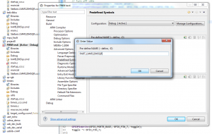
Oh, and to define the constant, you may want to go to project properties (I assume everyone is capable of creating an empty project already in CCS), and select Build / Advanced Options / Predefined Symbols / Add Pre-define NAME and type “PART_LM4F120H5QR” into the dialog. An example of how it should look like is given on the right.
Wrapping it all together
All right! We have everything more or less in place. The full source code becomes:
#include "inc/hw_types.h"
#include "inc/hw_memmap.h"
#include "driverlib/sysctl.h"
#include "driverlib/gpio.h"
#include "driverlib/timer.h"
#include "driverlib/pin_map.h"
int main(void) {
unsigned long ulPeriod, dutyCycle;
// 40 MHz system clock
SysCtlClockSet(SYSCTL_SYSDIV_5|SYSCTL_USE_PLL|
SYSCTL_XTAL_16MHZ|SYSCTL_OSC_MAIN);
ulPeriod = 1000;
dutyCycle = 250;
// Turn off LEDs
SysCtlPeripheralEnable(SYSCTL_PERIPH_GPIOF);
GPIOPinTypeGPIOOutput(GPIO_PORTF_BASE, GPIO_PIN_1|GPIO_PIN_2|GPIO_PIN_3);
GPIOPinWrite(GPIO_PORTF_BASE, GPIO_PIN_1|GPIO_PIN_2|GPIO_PIN_3, 0);
// Configure PB6 as T0CCP0
SysCtlPeripheralEnable(SYSCTL_PERIPH_GPIOB);
GPIOPinConfigure(GPIO_PB6_T0CCP0);
GPIOPinTypeTimer(GPIO_PORTB_BASE, GPIO_PIN_6);
// Configure timer
SysCtlPeripheralEnable(SYSCTL_PERIPH_TIMER0);
TimerConfigure(TIMER0_BASE, TIMER_CFG_SPLIT_PAIR|TIMER_CFG_A_PWM);
TimerLoadSet(TIMER0_BASE, TIMER_A, ulPeriod -1);
TimerMatchSet(TIMER0_BASE, TIMER_A, dutyCycle); // PWM
TimerEnable(TIMER0_BASE, TIMER_A);
while(1) { // The following code varies the duty cycle over time
TimerMatchSet(TIMER0_BASE, TIMER_A, dutyCycle++);
if(dutyCycle >= ulPeriod - 1)
dutyCycle = 0;
SysCtlDelay(50000);
}
}
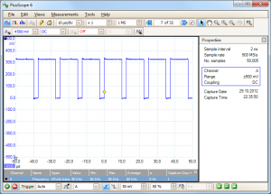
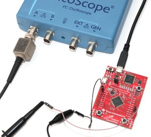
After wiring the Launchpad to my trusty old (you can see the dust in the post title image if you click it full size :) Picoscope, it’s easy to verify the code actually works:
That’s it! Based on this tutorial, it should be quite easy to set up more PWM signals, or once you realize that the Launchpad LEDs are located in PF1-3 that in turn can be controlled by T0CCP1, T1CCP0, and T1CCP1, you can also set up all kinds of cool color displays like in the Stellaris Launchpad demo program.
Oh, and if someone is able to figure out how in the hell am I supposed to set up timer-based PWM interrupts so I can get interrupted on both timer reset and match and figure out which one, please let me know. Based on some “quick” (one hour down the drain) tests, the PWM functionality stops working once timer interrupts get set up. You’d think it would be rather straightforward using Driverlib, but in that case you’d think wrong.
36 comments
jokkebk:
Cool, this post got featured on Hack a Day!
scompo:
As far as I know the pwm can generate interrupts just on compare, not on reset of the counter.
I’ve asked about it in the TI forums along with a question on the TimerSynchronize() function, right here: . Do you have any idea about how that works?
proteinman:
Thanks for putting this out there, it helped me alot.
proteinman:
//This code will PWM the leds
#include “inc/hw_types.h”
#include “inc/hw_memmap.h”
#include “driverlib/sysctl.h”
#include “driverlib/gpio.h”
#include “driverlib/timer.h”
#include “driverlib/pin_map.h”
int main(void) {
unsigned long ulPeriod_led_f1, dutyCycle_led_f1, ulPeriod_led_f2, dutyCycle_led_f2, ulPeriod_led_f3, dutyCycle_led_f3;
// 40 MHz system clock
SysCtlClockSet(SYSCTL_SYSDIV_5|SYSCTL_USE_PLL|
SYSCTL_XTAL_16MHZ|SYSCTL_OSC_MAIN);
ulPeriod_led_f1 = 1000;
dutyCycle_led_f1 = 1;
ulPeriod_led_f2 = 1000;
dutyCycle_led_f2 = 1;
ulPeriod_led_f3 = 1000;
dutyCycle_led_f3 = 1;
// Turn off LEDs
SysCtlPeripheralEnable(SYSCTL_PERIPH_GPIOF);
GPIOPinTypeGPIOOutput(GPIO_PORTF_BASE, GPIO_PIN_1|GPIO_PIN_2|GPIO_PIN_3);
GPIOPinWrite(GPIO_PORTF_BASE, GPIO_PIN_1|GPIO_PIN_2|GPIO_PIN_3, 0);
// Configure LEDs PortF as Timer outputs -> see pg 659 of datasheet
SysCtlPeripheralEnable(SYSCTL_PERIPH_GPIOF);
GPIOPinConfigure(GPIO_PF1_T0CCP1|GPIO_PF2_T1CCP0|GPIO_PF3_T1CCP1);
GPIOPinTypeTimer(GPIO_PORTF_BASE, GPIO_PIN_1|GPIO_PIN_2|GPIO_PIN_3);
// Configure timer 0 – this timer outputs to pf1 (led)
SysCtlPeripheralEnable(SYSCTL_PERIPH_TIMER0);
TimerConfigure(TIMER0_BASE, TIMER_CFG_SPLIT_PAIR|TIMER_CFG_B_PWM);
TimerLoadSet(TIMER0_BASE, TIMER_B, ulPeriod_led_f1 -1);
TimerMatchSet(TIMER0_BASE, TIMER_B, dutyCycle_led_f1); // PWM
TimerEnable(TIMER0_BASE, TIMER_B);
//Configure timer 1 – timer is split in half; A and B timers (16 bit)
SysCtlPeripheralEnable(SYSCTL_PERIPH_TIMER1);
TimerConfigure(TIMER1_BASE, TIMER_CFG_SPLIT_PAIR|TIMER_CFG_A_PWM|TIMER_CFG_B_PWM);
//Values and settings for Timer1(A) – this timer outputs to pf2
TimerLoadSet(TIMER1_BASE, TIMER_A, ulPeriod_led_f2 -1);
TimerMatchSet(TIMER1_BASE, TIMER_A, dutyCycle_led_f2); // PWM
TimerEnable(TIMER1_BASE, TIMER_A);
//Values and settings for Timer1(B) – this timer outputs to pf3
TimerLoadSet(TIMER1_BASE, TIMER_B, ulPeriod_led_f3 -1);
TimerMatchSet(TIMER1_BASE, TIMER_B, dutyCycle_led_f3); // PWM
TimerEnable(TIMER1_BASE, TIMER_B);
while(1) { // The following code varies the duty cycle over time, it cycles duty cycles at different rates
TimerMatchSet(TIMER0_BASE, TIMER_A, dutyCycle_led_f1++);
TimerMatchSet(TIMER1_BASE, TIMER_A, dutyCycle_led_f2=dutyCycle_led_f2+2);
TimerMatchSet(TIMER1_BASE, TIMER_B, dutyCycle_led_f3=dutyCycle_led_f3+4);
if(dutyCycle_led_f1 >= ulPeriod_led_f1 – 1)
dutyCycle_led_f1 = 0;
if(dutyCycle_led_f2 >= ulPeriod_led_f2 – 1)
dutyCycle_led_f2 = 0;
if(dutyCycle_led_f3 >= ulPeriod_led_f3 – 1)
dutyCycle_led_f3 = 0;
SysCtlDelay(200000);
}
}
scompo:
A solution to fire both interrupts on capture and on timer reset would be to use 2 syncronized timers one as PWM and the other just as a periodic one as suggested .
jokkebk:
Thanks for your input! Sorry that your comments took some time to appear, for some reason Akismet thought they were spam, which they definitely were not. :)
GMB:
Thank you!
Have you tried this code?
There is something wrong!
JimBob:
You might want to check out the Stellaris PinMux utility on the TI website. It helps in setting up the alternate pin functions. I have found the learning curve for Stellaris steep, owing largely to a dearth of (clear) documentation. Your example also cleared up an issue I just ran into while using the UARTs-some constants used by the pin mapping were indefined even though the compiler was finding the include file. One would assume that specifying the chip when the project was created would have resulted in PART_LM4F120H5QR being defined. Apparently not so. I cannot see any reason for this not being an automatic feature.
Labeeb:
What compiler are you using?It looks like you are using etheir CCS or IAR, this code is not compatible with etheir oneyou may have to enable the interrupt another way (gie bit), and you will have to change how the interrupt is called (#pragma)please let me know how you get it to work and i will update my post to add your changes
Astro75:
I made more user friendly methods for controlling pwm.
https://github.com/astro75/stellaris-pwm/blob/master/main.c
M.Fatih İNANÇ:
Hello,
The wrong line is;
GPIOPinConfigure(GPIO_PF1_T0CCP1|GPIO_PF2_T1CCP0|GPIO_PF3_T1CCP1);
It should be as follows;
ROM_GPIOPinConfigure(GPIO_PF3_T1CCP1);
ROM_GPIOPinConfigure(GPIO_PF2_T1CCP0);
ROM_GPIOPinConfigure(GPIO_PF1_T0CCP1);
And good point to add invert outputs;
// invert PWM outputs
TIMER0_CTL_R |= 0x4000;
TIMER1_CTL_R |= 0x4000;
TIMER1_CTL_R |= 0x40;
Misael Lafuente:
Thanks I was very helpfull for me. I also spended so much time trying to configure the PWM output
Ivan Babatov:
Here is how I managed to use interrupts with timer0 in PWM mode. Hope it helps.
in main(void) :
/*#include all necessary headers from previous examples */
#include “inc/hw_timer.h” /* to gain access to TIMER_O_TAMR, etc. timer registers */
/* As in the previous examples – setup clock, enable used peripherals, setup GPIOs here */
TimerConfigure(TIMER0_BASE, TIMER_CFG_SPLIT_PAIR | TIMER_CFG_A_PWM | TIMER_CFG_B_PWM);
/* Make corresponding CCP pin go HIGH (going LOW is the default legacy operation) in the beginning of the PWM period (TAPLO = 1)
* (not really needed if we only care for interrupts);
* Make the changes to match registers take effect on the start of the next PWM period, not immediately (TAMRSU = 1);
* Make the changes to reload (period) registers take effect on the start of the next PWM period, not immediately (TAILD = 1);
*
* NOTE: the PWM with interrupts should work even without this line, but the datasheet says it’s better to set the MR this way */
HWREG(TIMER0_BASE + TIMER_O_TAMR) |= (TIMER_TAMR_TAMRSU | TIMER_TAMR_TAPLO | TIMER_TAMR_TAILD);
/* Make the timer generate events on both rising and falling PWM edges */
TimerControlEvent(TIMER0_BASE, TIMER_A, TIMER_EVENT_BOTH_EDGES);
/* Setup interrupts */
TimerIntEnable(TIMER0_BASE, TIMER_CAPA_EVENT);
IntEnable(INT_TIMER0A);
IntMasterEnable();
TimerEnable(TIMER0_BASE, TIMER_A);
while(1)
{
/* main loop here */
}
Ivan Babatov:
Wrong again :( :(
Last attempt, if this does not work, please erase all the mess and mail me to (address removed) – I will send you the project.
void Timer0IntHandler(void)
{
uint32_t tmr_val;
uint32_t tmr_match;
uint32_t InterruptStatus = TimerIntStatus(TIMER0_BASE, true);
if(InterruptStatus & TIMER_CAPA_EVENT)
{
TimerIntClear(TIMER0_BASE, TIMER_CAPA_EVENT);
/*get the 24-bit current value of the timer's counter*/
tmr_val = TimerValueGet(TIMER0_BASE, TIMER_A);
/* compose the 24-bit match value */
tmr_match = TimerPrescaleMatchGet(TIMER0_BASE, TIMER_A)*65536UL
+ TimerMatchGet(TIMER0_BASE, TIMER_A);
if(tmr_val > tmr_match)
{
/* the interrupt is caused by a reload (start of a new PWM period) */
/* Turn the red LED on */
GPIOPinWrite(GPIO_PORTF_BASE, GPIO_PIN_1, GPIO_PIN_1);
}
else
{
/* the interrupt is caused by a match (end of a PWM pulse) */
/* Turn the red LED off */
GPIOPinWrite(GPIO_PORTF_BASE, GPIO_PIN_1, 0x00);
}
}
}
Ivan Babatov:
Ah, this time it’s OK. I really hope this will be of some use to someone :)
Ivan Babatov:
Please, look below for the Timer ISR
Anthony:
Thank you very much I was able to get this working but may I ask for future reference…What is the point of defining the symbol “PART_LM4F120H5QR” ? Is it so that the compiler knows which device to look under in the pin_map? That’s just my wild guess since I was finding that CSS kept telling me GPIO_PF1_T0CCP1 was an unrecognized symbol up until I pre-defined the PART_LM4F120H5QR symbol in the project options.
igor:
There is an error in the tutorial code
under Step 1: Setting up the timer0 PWM mode
In the second code box dutyCycle is never used.
I believe the line that reads
TimerMatchSet(TIMER0_BASE, TIMER_A, ulPeriod / 2);
should read
TimerMatchSet(TIMER0_BASE, TIMER_A, dutyCycle);
as it does in the final code box.
Greg Oberfield:
It’s so that the proper pin mappings from pin_map.h are pulled into the project. Believe me, took a little bit for me to figure that out the first time until I looked in the file, saw all the defines and went “aww hell!”
Savita:
Hey all!. This one has helped me a lot. i want to do a down counter. So i need to use TimerB of the timer0 and use the same way as above?
Barty79:
To configure interrupts for PWM:
TimerIntEnable(TIMER0_BASE, TIMER_CAPA_EVENT);
TimerControlEvent(TIMER0_BASE, TIMER_A, TIMER_EVENT_POS_EDGE);
TimerIntRegister(TIMER0_BASE, TIMER_A, Timer0AIntHandler);
void Timer0AIntHandler(void) {
TimerIntClear(TIMER0_BASE, TIMER_EVENT_POS_EDGE);
...
}
Barty79:
Sorry, it should be:
void Timer0AIntHandler(void) {
TimerIntClear(TIMER0_BASE, TIMER_CAPA_EVENT);
...
}
Lippy:
Hey I love this tutorial!!! Great work. I do have two questions though.
1. Can you change the frequency of the PWM wave? Currently mines is at 40 kHz which is great but it would be nice to change the frequency for applications like servo driving.
2. Can you achieve a 0% duty cycle? when I enter in 0% (1000) the PWM wave goes to 100% (3.3V)
Thanks for your help
Lippy:
Excuse my stupidity, for some reason I completely missed ulPeriod lol
Brandon:
Thanks for the detailed write-up!
Dutchpainter:
I had the same problem, changed the mentioned line to:
GPIOPinConfigure(GPIO_PF1_T0CCP1);
GPIOPinTypeTimer(GPIO_PORTF_BASE, GPIO_PIN_1);
GPIOPinConfigure(GPIO_PF2_T1CCP0);
GPIOPinTypeTimer(GPIO_PORTF_BASE, GPIO_PIN_2);
GPIOPinConfigure(GPIO_PF3_T1CCP1);
GPIOPinTypeTimer(GPIO_PORTF_BASE, GPIO_PIN_3);
that seems to work. See also page 159 of the Stellaris Peripheral Driver Library
jokkebk:
Thanks for noticing that. Fixed it now.
jokkebk:
Yes, one would assume the correct part constant is defined by other include files based on build target platform (one needs to set it when creating project, anyways), but no, you actually have to define that yourself. Very counterintuitive and there’s no mention of that in the documentation..
Larissa:
Just wanted to say thank you so much for such a detailed and throughout write-up.
Side note: We did include the PWM in the next revision of the board :-), but this helps give all of the Stellaris ones in the ecosystem a way to do it!
Thank you again!
Emmanuel:
Thank you very much. I really needed the info
José Tejero:
The wrong is
while(1) { // The following code varies the duty cycle over time, it cycles duty cycles at different rates
TimerMatchSet(TIMER0_BASE, TIMER_A, dutyCycle_led_f1++);
It should be
while(1) { // The following code varies the duty cycle over time, it cycles duty cycles at different rates
TimerMatchSet(TIMER0_BASE, TIMER_B, dutyCycle_led_f1++);
yakdag:
both GPIOPinConfigure(GPIO_PF1_T0CCP1|GPIO_PF2_T1CCP0|GPIO_PF3_T1CCP1); and ROM_GPIOPinConfigure(GPIO_PF3_T1CCP1);
ROM_GPIOPinConfigure(GPIO_PF2_T1CCP0);
ROM_GPIOPinConfigure(GPIO_PF1_T0CCP1); is same mistake; #20 identifier “GPIO_PF3_T1CCP1” is undefined
what would be problem. I’m stuck here. ı m using CCS 5.3
prasad chitta:
hi….
I need a small nformation, Is pwm code of stellaris launch pad work on c2000 launch pad…?
Dasaev:
Hi Ivan, may you send me your project please. I need it
Thank you
Ivan Babatov:
Hi,
I will gladly send you the project, I just need to get home – its on the PC there. However…. I would need your e-mail, and I am afraid this site won’t let you publish it. Try mailing me at babatowatyahoodotcom (hope this does not get filtered).
Looking forward to hearing from you,
Ivan.
Sam:
Having the same error: GPIO_PF3_T1CCP1 is undefined. Any ideas?