Simple FAT and SD Tutorial Part 3
Finally back! Sorry for taking a while, but getting the SD cards to work required quite a bit of research! In this part of the tutorial, we’ll start talking with the SD card. Once you get that working, adding the FAT library developed in the previous part will be easy.
This tutorial will most likely be the most challenging covered in my blog so far, so beware: You may need to do some troubleshooting on this one! If you encounter problems, I recommend you to ask any questions at the AVR Freaks tutorial forum topic, so more people might be able to help you than just me!
Basic hardware setup: ATmega88 with UART console
The 3.3V UART I covered just a while ago will form the basis for this project. Only change we will be doing is to replace ATtiny2313 with ATmega88. This is because SPI, SD and FAT code will eat up almost 3 kB of program memory, and the ATtiny chips with that much program memory and separate RX/TX and SPI pins are not that common, while ATmega88 is readily available (48 and 168 work as well, of course). To accommodate the new chip, the following hardware changes are made to the ATtiny2313 version:
- ATmega88 will require two ground connections
- In addition to VCC, also AVCC for analog circuitry needs to be wired to VCC
- Additional capacitor between AVCC and GND is recommended (I used 10 uF)
- Programming header MOSI/MISO/SCK are also in different place
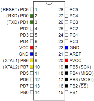
I assume you are by now capable of wiring the ATmega correctly, but just to make things easier, I attached a pinout diagram with the RXD/TXD wires marked with green (they go to MAX3232 or similar RS232 circuit), VCC/GND marked with red/blue, crystal pins with yellow and SPI/programming pins with black. These are all pins that need to be connected in this project.
Also, the UART facilities of ATmega family differ a bit from ATtiny2313, so our helper methods needs tweaking:
void USARTInit(unsigned int ubrr_value) {
    //Set Baud rate
    UBRR0H = (unsigned char)(ubrr_value >> 8);
    UBRR0L = (unsigned char)(ubrr_value & 255);
    // Frame Format: asynchronous, no parity, 1 stop bit, char size 8
    UCSR0C = (1 << UCSZ01) | (1 << UCSZ00);
    //Enable The receiver and transmitter
    UCSR0B = (1 << RXEN0) | (1 << TXEN0);
}

char USARTReadChar() { // blocking
    while(!(UCSR0A & (1<<RXC0))) {}
    return UDR0;
}

void USARTWriteChar(char data) { // blocking
    while(!(UCSR0A & (1<<UDRE0))) {}
    UDR0=data;
}
And of course the fuses are different for our 20 MHz clock than in ATtiny2313. I used lfuse of FF and hfuse of DD. Before you proceed any further, I advice you to flash the ATmega88 with the simple echo program from tutorial to see that the ATmega88 UART works as it should. You can get that here.
Hardware note: If you don’t have a 3.3V capable MAX3232 or similar IC, but have a 3.3V capable LCD, you could just replace the printout routines with LCD writes, and use switches as inputs instead of a terminal program. Also, see my level shifting article if you’d like to run ATmega88 from 5V but SD card from 3.3V, the choice is yours!
Wiring the SD card to the project
For this project, you’ll need a empty SD card of 1 or 2 GB (smaller ones also OK) formatted to FAT16 (Windows just says “FAT”, just do not select FAT32!). Copy a small text file named README.TXT to the root folder. Note that the file needs to be in ALL CAPS, otherwise it’ll not be found by our case-sensitive code later on. Also a microSD card will do, if you have a adapter card or suitable connector (for example SparkFun sells several models). For wiring the card to a breadboard, you have a few easy alternatives:
- If you use a microSD card and have a spare SD adapter, just solder wires or pin header to it, just like in this tutorial. Nice ad-hoc microSD breadboard adapter!
- Even easier if you have a 2-row pin header, just place the SD card between the rows and tighten with a piece of cardboard in the back, just like here
I chose option 2. I had some issues with some cards not responding to SPI, and I found out that the code started working once I gently pushed the SD card towards the pins while the system was operating – adding a thin paper in addition to the piece of cardboard fixed this, so if you have communication problems, first try to add some stuffing!
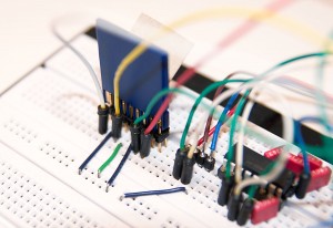
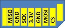
Once you have means to plug the SD card to breadboard, you need to connect it to ATmega88. You can see the pinout above. The GND and 3.3V pins are easy, just connect them to the relevant power rails in the breadboard (remember: SD cards will likely be damaged if you operate them at 5V). MISO, MOSI and SCK go to the matching ATmega88 pins. CS (Circuit Select) is connected to the SS (Slave Select, essentially another name for the same thing) pin. Unmarked pads are not connected to anything. See the full size article photo for an example SD card wired to breadboard – white wire is MISO, yellow is SCK, green is MOSI and red is CS/SS.
The SD card connected to ATmega88 SPI pins sometimes interferes with MCU programming – if you get checksum errors with AVRdude, disconnect SD card, flash, and connect the SD card again!
SPI communication with the SD card
The hardware is ready, but now we’ll need to develop some software to talk with the SD card. If you have a Bus Pirate (I recently bought one, it’s really neat :), you could try it manually at this point. Even if you don’t, I warmly recommend skimming through Nathan Dyer’s BusPirate SD article, as it shows the four commands we need for talking with the SD card, as well as the expected response. In BusPirate syntax, the commands are:
- Init and go to SPI mode:
]r:10 [0x40 0x00 0x00 0x00 0x00 0x95 r:8] - Initialize card:
[0x41 0x00 0x00 0x00 0x00 0xFF r:8] - Set transfer size:
[0x50 0x00 0x00 0x02 0x00 0xFF r:8] - Read sector:
[0x51 0x00 0x00 0x00 0x00 0xFF r:520]
The protocol used to communicate with the card is called SPI (Seriap Peripheral Interface). It’s the same one that’s used to flash AVR chips. For our needs it’s enough to know that our ATmega88 will be the “master” of the SPI bus, and the SD card will be the “slave”. To get the slave to listen, we pull the Circuit Select (or Slave Select) line low, and start generating a clock signal on the SCK line. Every clock beat, the master sends a bit using the MOSI (Master Out, Slave In) wire, and the slave sends a bit using the MISO (Master In, Slave Out). This is repeated eight times, after which a full byte has been transferred by both parties. When communicating with a SD card, data that is received while sending can be ignored, and when receiving data, the master should send all ones (0xFF as a byte).
If you want to learn more about SPI (and I recommend at least cursory look), I recommend you to read the Wikipedia article on SPI. There’s some extra details like clock polarization and phase that need to be the same for both master and slave, but knowing that the “out of the box” setup of ATmega SPI hardware works with SD cards, we don’t need to consider them here.
The BusPirate syntax seen above is rather simple: “[” means that the CS line is activated (pulled low) and “]” means the opposite (deactived / pulled high). A hex in SPI mode means that hex is sent to the slave over SPI. “r” means a byte is read from the slave (while sending a 0xFF, because SPI operations always read and write at the same time). “:8” means the command before it is repeated eight times, and it can be used for both read and write operations. So the “Go to SPI mode” command actually does the following:
- Pull CS high (deselect)
- Read 10 bytes (basically sends CLK pulse 80 times to give SD card time to initialize)
- Pull CS low (select)
- Send 0x40 (“go to SPI mode” command, CMD0)
- Send four zero bytes (SD protocol has 4-byte arguments)
- Send 0x95, the CRC checksum of the command and argument just sent
- Read eight bytes and print them out (while sending 0xFF to the card)
- Pull CS high (deselect)
The steps 1-2 are unique in the start, and are not actually part of standard SD command syntax – they just make sure the SD card receives 80 clock ticks before we send any commands. Not so hard, wasn’t it? While the SD card is processing our command, it will reply with 0xFF and once it’s ready, it’ll respond with 0x01. Then it’ll go back to sending 0xFF (the same byte we’re sending to it while reading, by the way). So if you look at the BusPirate tutorial you’ll see that a valid response of 8 bytes could be “0xFF 0x01 0xFF 0xFF 0xFF 0xFF 0xFF 0xFF”.
If you want to learn more about the SD protocol, there’s a simplified specification sheet available from SD Association without signing an NDA.
Utilizing the SPI hardware of ATmega88
I have some good news: The ATmega SPI hardware is very easy to use and understand. Basically, we just need to set the MOSI, SCK and SS pins as outputs, and set some bits in SPI control register, SPCR. See ATmega88 datasheet for details, this code is quite straight from there (except MISO pullup, I added that just to be sure):
#define CS (1<<PB2)
#define MOSI (1<<PB3)
#define MISO (1<<PB4)
#define SCK (1<<PB5)
#define CS_DDR DDRB
#define CS_ENABLE() (PORTB &= ~CS)
#define CS_DISABLE() (PORTB |= CS)

void SPI_init() {
    CS_DDR |= CS; // SD card circuit select as output
    DDRB |= MOSI + SCK; // MOSI and SCK as outputs
    PORTB |= MISO; // pullup in MISO, might not be needed

    // Enable SPI, master, set clock rate fck/128
    SPCR = (1<<SPE) | (1<<MSTR) | (1<<SPR0) | (1<<SPR1);
}

unsigned char SPI_write(unsigned char ch) {
    SPDR = ch;
    while(!(SPSR & (1<<SPIF))) {}
    return SPDR;
}
Note how I defined two macros, CS_ENABLE() and CS_DISABLE() that’ll take the CS line low and high, respectively. Also, the SD SPI may not work on higher SPI clock frequencies so a conservative divider of 128 is used instead of for example 16. Using the above functions, ]r:10 becomes:
CS_DISABLE();
for(i=0; i<10; i++) // idle for 1 bytes / 80 clocks
    SPI_write(0xFF);
Similarly, we can create a general function for executing a SD command like [0x40 0x00 0x00 0x00 0x00 0x95 r:8] – send a command byte, then argument dword, followed by CRC byte and finally some reads:
void SD_command(unsigned char cmd, unsigned long arg,
                unsigned char crc, unsigned char read) {
    unsigned char i, buffer[8];

    CS_ENABLE();
    SPI_write(cmd);
    SPI_write(arg>>24);
    SPI_write(arg>>16);
    SPI_write(arg>>8);
    SPI_write(arg);
    SPI_write(crc);

    for(i=0; i
``
Note that the "& 255" part after arg>>16 etc. can be omitted because SPI_write takes a byte argument and any bits above the bottom 8 are truncated.
I added the above fragments of code to the USART test, and added a few printout commands (uwrite_str for printing out strings over RS-232 and uwrite_hex for bytes in hex format). I thought it would be nice to interact with the program manually for a change, so the main loop just waits for "1", "2" or "3" to be typed into terminal, and executes one of the commands I mentioned above:
while(1) {
    switch(USARTReadChar()) {
    case '1':
        SD_command(0x40, 0x00000000, 0x95, 8);
        break;
    case '2':
        SD_command(0x41, 0x00000000, 0xFF, 8);
        break;
    case '3':
        SD_command(0x50, 0x00000200, 0xFF, 8);
        break;
    }
}
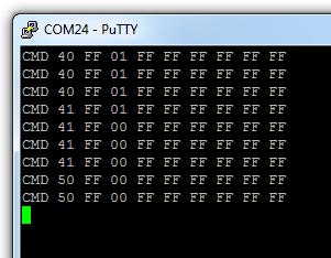
I tried each of the commands - 1, 2, and 3 a few times. Here's the output - if you check against the BusPirate tutorial I linked above, we can see that it's working! Download the spi88.c yourself and flash it to try it out yourself:
As an excercise, you could already try adding a new function for the fourth command that will read a sector from SD card. For this, you'll just need to write the command 0x51 (read data) with argument that is the data offset (start with 0 to dump the first sector) and CRC of 0xFF (SPI mode does not check CRC so we always send 0xFF after setting the SPI mode...). After that, instead of just reading 8 bytes, you read until you get 0x00 from SD card to indicate command has been processed, and then wait for 0xFE to indicate data start. Then you just loop for 512 bytes, printing them out as you go, and read additional two bytes (CRC).
In the next part of the tutorial, we'll do this and more: Combine the FAT library to our SD reading code to get a full-fledged SD reading library!
Finally, special thanks to Mark for his donation that I used to cover part of the BusPirate purchase costs - this tutorial would've likely taken quite a while longer without the debugging help I had from that tool!
Proceed to the next part of this tutorial
``


