Using Arduino Uno as ISP
One exciting piece of hardware I received with my Digikey order was an Arduino Uno board (R3). There was conflicting information whether or not it could be used as an ISP (in-system programmer), so I decided to see for myself. It turned out that with just one tweak, I could use the $26 device to program my AVR chips, essentially eliminating the need for a separate ISP such as $22 USBtiny!
This is obviously good news for any beginner with a budget, so I decided to write a short tutorial on how to do it. I used my USB password generator as a guinea pig for this project, so if you have wanted to try that out, this post also doubles as tutorial on how to build it on breadboard (good idea in any case before soldering it anywhere). Read on for details!
Minimal circuit for AVR-powered USB

For this exact project, you’ll need the following components (of course you can also build something else, as long as the Arduino can power it):
- ATtiny45/85 (the 20PU version, not the low-voltage one)
- 2 resistors, 68 ohm
- 2 pullup resistors, 2k2 and 4k7 ohms
- USB connector (instructions how to build it)
- Breadboard and wire
- 2 zener diodes, 3V6, 0.25W (too much watts and it might not work)
If you’re really cheap, you could probably use just one pullup, wiring it to RESET while programming and then to D+ after you’re ready. Click the image for larger version, here’s the schematic if you need it.
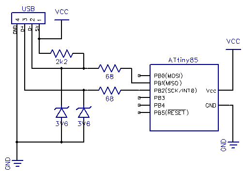
Update: As Ross McKenzie pointed out in the comments, 0.1 uF capacitor between VCC and GND should also be included. It seems to work without it most of the time, but it would be safer to have one there (to ensure the AVR chip being programmed gets a steady supply of power).
Wiring the Uno for Programming
If you haven’t flashed AVR chips before, it might be useful to know that the method used here is called serial programming with 6 pin interface. With dedicated ISP programmers you have the option to power the chip yourself (for example from external 3.3V source), but with Arduino as ISP, the safest bet is to power the chip from Arduino 5V and GND power connections.
In addition to powering the chip, you should know where the MOSI, MISO and SCK pins are in your microcontroller of choice. You can find this information from very beginning of Atmel’s datasheets, along with rather clear instructions for how to power the chip (for ATtiny45/85 we only need VCC and GND but some ATmegas for example have multiple VCC/GND pins that need to be connected as well as the AVCC pin). Here’s the pinout of ATtiny45/85 for reference:

Here are the connections you need to make – note that because Arduino is already supplying 5V, I have detached the USB connector and used two jumper wires from the power rail to the breadboard rows 14 (VCC) and 17 (GND, behind the green wire). This is because the USB connector seemed to provide slightly higher voltage than the Arduino (about 0.1V more), and I thought it would be safest not to wire both at the same time, as current flowing from USB to Arduino circuit may not be such a good idea.
| Arduino pin | Circuit pin | Explanation |
|---|---|---|
| 5V, red | VCC | Used to power the chip during programming with same voltage as the programmer |
| GND, blue | GND | Common ground |
| 10, orange | RESET | This line is pulled LOW to start programming |
| 11, green | MOSI | “Master out, slave in” – used for data from Arduino to chip |
| 12, yellow | MISO | “Master in, slave out” – used for data from chip to Arduino |
| 13, white | SCK | “System clock” – used synchronize the (SPI) data communications |

Programming
Once everything is wired up, you only need to upload the ArduinoISP sketch to your Arduino. If you’re running the 1.0 version of the Arduino IDE, there was some kind of timing/serial buffer/library mismatch and you need to tweak heartbeat() function to reduce the delay(40); to delay(20);. I don’t exactly know the cause for this, but some sources talked about buffer issues and it just might be that a shorter delay avoids filling some transmission buffer. Older 0022 version worked “out of the box”.
After flashing, your ‘duino should work as avrisp-compatible programmer for avrdude (and most likely also AVR Studio):
avrdude -P com18 -b 19200 -c avrisp -p attiny45 -U flash:w:main.hex
I’ve updated the USB password project zip to also contain a Makefile.uno that uses the Uno as a programmer. Furthermore, to help updating the fuses I added a new build target “fuse”. So once you’ve got everything wired up, just go to the directory and type the following commands to update fuses and flash the USB password firmware:
make -f Makefile.uno flash make -f Makefile.uno fuse
That’s it! You are now equipped to flash any 8-bit AVR chip, anywhere, anytime (provided you carry your Arduino around, of course) with firmware of your choice.
Where next + sponsor appreciation
Thanks for reading! I’d also like to remind all readers, that if you have a topic in mind you’d like me to cover, I’m taking suggestions via comments and e-mail (jokkebk at codeandlife.com). I’ll also take this opportunity to thank Martin, for the first donation supporting this blog. I really appreciate it! I already spent the donation on parts for project I’m hoping to cover here in the future. :)