Code and Life

Programming, electronics and other cool tech stuff

Supported by

Supported by Picotech

7 Segment Multiplexing With ULN2003 & PNP Transistors

The reason a started my electronics hobby was that I wanted to build a chess clock. Lacking a proper LCD display, I chose to multiplex several 7-segment displays. Most sources in the net did not specify hardware at all, and those that did were driving the segments with a 74HC595 shift register and using NPN transistors to enable one common cathode display at a time. However, if you look at 74HC595 specs you’ll notice that it’s not designed to source the amount of current that is required to drive several multiplexed 7-segment displays. It might work, but no one can say for how long!

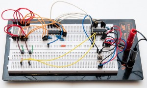
It took me a while to find a good, inexpensive and readily available alternative. I finally found it in ULN2003, which is inexpensive darlington array that can drive 500 mA from each of its pins. So I decided to write a little tutorial on 7 segment multiplexing that walks through all the needed hardware and software in detail. Here’s what we’ll build (click for a larger image):

For this tutorial I assume you know how to connect ATtiny2313 to a programmer and flash it with custom software. You’ll learn as much in IMakeProjects.com’s AVR tutorial. You’ll also need the following components:

  • ATtiny2313 (actually, any AVR chip with 10 output pins will do)
  • ULN2003, 7-channel darlington array (NPN, i.e. current sinks)
  • 7 resistors, 330 ohm
  • 2 seven segment displays, common anode
  • 2 PNP transistors, e.g. BC558B, but almost any will do
  • 2 resistors, 2.2 kohm
  • 4.7 kohm pullup resistor(or similar value)
  • 6-pin programming header
  • A breadboard and jumper wires
  • 5V DC voltage source (USB is one option)

Seven segment display basics

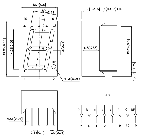
A seven segment display is basically just 8 LEDs (most include a decimal point) wired so that they share a common cathode or anode. Like normal LEDs, you need current-limiting resistors in series. Each segment needs its own resistor, otherwise LEDs get dimmer the more segments are lit. Number segments are labelled a-g and connected to “side pins”, whereas common cathode/anode occupy the center pin on top and bottom of the display – they are internally connected so we only need to wire one of them.

From the datasheet picture above, you can see how the pins are numbered (top left schematic), and which pin is connected to which segment (bottom right diagram).

ULN2003

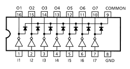
The chips I got from Partco had the exact model of ULN2003APG. The datasheet tells that the chip has 2.7 kohm resisors on input side, so I1-I7 can be directly wired to PD0-PD6. Here’s how the pinout looks like:

In this tutorial, we’ll be wiring the “a” segments of both seven segment displays to a 330 ohm current-limiting resistor connected to O1 (only one display is on at a time so two displays can share a resistor even if two segments cannot). “b” segments are wired via another 330 ohm resistor to O2, and so on. Pretty simple!

Multiplexing common anode displays

Multiplexing means that you are actually switching only one display on at a time, but you do it so fast (at least 60 Hz) that the eye does not notice it. Easiest way to switch on a display is with a transistor, so the microcontroller does not need to sink/source all the current flowing through LEDs – even with only two displays it would most likely exceed MCU specs.

Most examples on the net use common cathode displays, in which case NPN transistor is called for, but the ULN2003 which we are using here for each segment is a current sink, which means individual segments need to be wired to it on “minus side” – so we need a common anode type of display. Because the “multiplex switch transistor” is now on VCC side instead of GND side, NPN transistor would not work. So we are using PNP transistor instead. See this article for more details on PNP switching (the previous page of that link shows NPN switching, by the way).

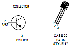
Note that for a PNP transistor, you wire the emitter to VCC (in this image it’s pin 3) and collector to the common anode of the display.

Hardware setup and schematic

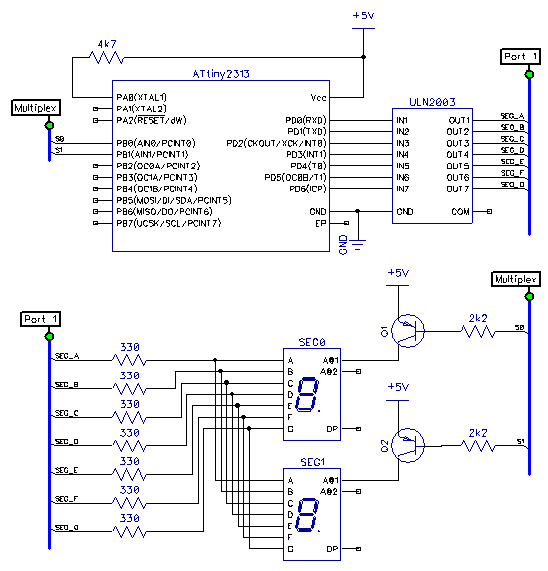
For simplicity, I chose to the 7-pin port D of ATtiny2313 for selecting the segments, and PB0+PB1 for first and second digit display, respectively. Here’s the full schematic – the wiring of the 6-pin programming is omitted for clarity:

Update: Transistor symbol had the arrow pointing the wrong way (i.e. NPN, not PNP). Fixed.

Good order to wire these is the following:

  1. Start with the ATtiny2313 and it’s VCC, GND and RESET pullup resistor
  2. Add the 6-pin header and wire it to ATtiny, VCC and GND
  3. Add power and you can now test if you can program the ATtiny
  4. Add ULN2003 and 330 ohm resistors, connect the ground pin and wire ATtiny PD0..PD6 to I1..I7
  5. Add the first 7 segment display, and wire segments a-g to the 330 ohm resistors
  6. Tip: Program ATtiny so it outputs VCC from all port D pins (DDRD=0x7F; PORTD=0x7F;) and temporarily wire seven segment display’s common anode straight to VCC – now it’s easy to start wiring segments to the correct resistors, as a segment lights up as soon as you plug a jumper wire in!
  7. Add the second 7 segment display and connect the “a” segments of both displays, then “b” segments and so on
  8. At this point you can test if everything except the transistor switching works by wiring the anodes straight to VCC and blinking the LEDs with ATtiny
  9. Finally, add the transistors, connect their emitters to VCC, bases to PB0 & PB1 and collectors to display 1 & 2, respectively

Software

First thing to tackle is the display of numbers 0 to 9 using PORTD. With a few defines it’s easy to construct the necassary bitmasks:


#define SEG_ALL 0x7F
#define SEG_A 1
#define SEG_B 2
#define SEG_C 4
#define SEG_D 8
#define SEG_E 16
#define SEG_F 32
#define SEG_G 64

// display given digit in seven-segment display
void display(uint8_t n) {
    switch(n) {
        case 0: PORTD = SEG_ALL-SEG_G; break;
        case 1: PORTD = SEG_B+SEG_C; break;
        case 2: PORTD = SEG_ALL-SEG_F-SEG_C; break;
        case 3: PORTD = SEG_ALL-SEG_F-SEG_E; break;
        case 4: PORTD = SEG_F+SEG_G+SEG_B+SEG_C; break;
        case 5: PORTD = SEG_ALL-SEG_B-SEG_E; break;
        case 6: PORTD = SEG_ALL-SEG_B; break;
        case 7: PORTD = SEG_A+SEG_B+SEG_C; break;
        case 8: PORTD = SEG_ALL; break;
        case 9: PORTD = SEG_ALL-SEG_E; break;
        default:PORTD = 0; break;
    }
}

To have something useful to display, we’ll make the 16-bit timer1 count seconds which we will then display. For multiplexing, we’ll use 8-bit timer0 with prescaler of 8 and overflow interrupt. At 1 MHz (ATtiny2313 with default fuses), this results in 10^6 / 256 / 8 = ~500 calls per second. Each call, we turn off one display, reconfigure the segments to light up, and turn on the other display. This results in ~250 Hz refresh rate which should be plenty:


volatile uint8_t timer_seconds = 0;

ISR(TIMER1_COMPA_vect) { // 1 Hz counter
    timer_seconds++;
} 

volatile uint8_t active_display = 0;

ISR(TIMER0_OVF_vect) { // multiplex code
    PORTB |= (1 << active_display); // display OFF (VCC at base)

    active_display ^= 1; // toggle between 0 and 1
    
    if(active_display == 0) // prepare next digit
        display(timer_seconds % 10);
    else
        display((timer_seconds/10) % 10);
	
	PORTB &= ~(1 << active_display); // display ON (GND at base)
}

Note that because we are using a PNP transistor, we actually need to "write 1" to a pin to switch the current off! Now all we need to do is initialize the ports and timers and let the interrupts do their magic:


int main(void) {	
	// initialize ports
	DDRD = SEG_ALL; // PD0-PD6 as outputs
	DDRB = (1<

This is actually all of the code needed for the project. Just add includes to avr/io.h and avr/interrupt.h and you are all set. For the lazy ones, here's the complete source file.

Once you have this one working, it is of course easy to add a shift register like the 74HC595 in front of ULN2003 to reduce the amount of pins needed on AVR side (3+2 required with a '595, and using I2C I/O expander it could even be reduced to 2+2 - and of course you can do the same on multiplex side to switch up to 8 displays with only 2-3 pins).

Thanks for reading! If you liked the tutorial, do subscribe to the RSS feed, there's more in the works. :)
28 comments

Alnoor:

Just wanted to let you know, that your transistors are drawn incorrectly.

Alnoor

jokkebk:

Thanks Alnoor! I hadn’t noticed the arrow was pointing the wrong way – DipTrace does not have a general PNP/NPN symbols but instead a few hundred different part codes and I had accidentally picked an NPN one. :)

Anik:

hey thanks for this!
but can u tell me why u left the CD+ input for 2003 open? shudnt it be +12v?

jokkebk:

The common pin is only connected to output via diodes and I think the main function of those diodes is to provide a path for backcurrent when driving inductive loads. A LED is not an inductive load, so the diodes are not needed, and thus then pin 9 can be left unconnected (connecting it to anything between VCC and 12 V, for example, would never result in any current flowing through that pin).

I even remembered there’s a mention of this in the datasheet, but couldn’t find it when I did a quick peek. Must’ve been somewhere else where I read that…

hamza:

Hii I am new in electronics,… Can u please tell me that how to use this code ??

jokkebk:

If you have the necessary parts and AVR programmer, you can get WinAVR package, compile it and use avrdude to flash it to the MCU. :) There should be plenty of tutorials on getting started with AVR microcontrollers, after you can blink a LED, you can then return here.

Nestor Oak:

Thanks for great article! But this scheme does not count EXACT seconds, does it? I’ve been making similar project and tried your programm too, this clock is slow for 1 second for every minute!

jokkebk:

No it doesn’t, the internal RC oscillator in AVR chips is usually about 1 % off, as you experienced yourself. Adding a crystal oscillator as a clock source does improve the accuracy very much (to the same level as digital watches).

Also, if you’re using just one chip in a rather constant temperature, you can measure the error and calibrate the timer routines to achieve better accuracy, at least you should be able to get less than second in a minute.

Nestor Oak:

What if I simply make a software correction of time? For example, I extract 1 second from current time every minute (rougly). Is it a good way?

Nestor Oak:

Ah, of course I meant I add 1 second to my watch time

jokkebk:

If you’re not displaying the seconds and only care for minutes, then yes. If not, I’d rather adjust the magic value of OCR1A = 15625 – when you decrease it by 1 %, the clock goes 1 % faster and vice versa.

jokkebk:

Or to correct myself: The clock runs the same speed as always, but the timer interrupt is called slightly faster/slower when you decrease/increase the value of 15625. It also allows for much finer control than adding 1 second each minute.

Nestor Oak:

Oh, it’s very hard to calibrate a clock. I need to know what is exact slowing time, but I can’t start the microcontroller with its program and stopwatch on my cellphone completely simultaniously…

Antonio Rivero:

Great article thanks! just one doubt What if the leds are 12V @40mA 3 led bars (I believe the code is STR33R) I think the ULN can handle it but what about the PNP transistor and its base resistor? How can I calculate for the necessary changes ? thank you so much in advance

jokkebk:

If you’re using a simple transistor driver and a resistor to regulate current, you’ll need something that can handle at least the 13-14V voltage (assuming the resistor drop 1-2V). I haven’t checked ULN2003 specs for that. Also, I’m not positive that the PNP transistor can be turned off with MCU 5V voltage anymore, as 14V >> 5V – I’d google a bit on “transistor level conversion” and find a few examples, I recall additional transistor can be used for this.

Don’t have much practical experience on LED strips, so I wish you luck!

Philip:

Hey,
Nicely written article, I would like to experiment on using the 74HC595 shift register too. I have look into the data sheet for the 595 but it doesn’t seems to have a enough pins to separate input and output. I think I can connect the two 7 segment LED like you did in the schematic. But I’m not sure how to connect the ATtiny2313 to the 595 and then to the 7 segment display. Do you haven any suggestion on how to do so?

Joonas Pihlajamaa:

Thanks! The 595 datasheet does provide enough information so I was able to decipher it when just starting electronics, so I’d try either that, or one of the tutorials out there. For example “74HC595 tutorial” had a promising first result on this tutorial: http://arduino.cc/en/tutorial/ShiftOut it should be quite easy to adapt for raw AVR. Good luck!

Philip:

Hi,
Thanks for your advice. I’m very new to electronics and not really sure did I read the datasheet correctly. Therefore though I’ve cleared up some problems I had after reading the datasheet and the link you’ve recommended, I got confused on which resistors should I use and couple of questions also arises that I could not find the answer to. So I hope could I get some advice here. I’ve adapted your schematic, but instead of ULN2003 I’m using a 595shift register. I’ll be using the Q1-Q7 pin of the 595 as output.
Components I decided to use:
1) ATtiny2313

2) Kingbring 7segment LED (Green), DC forward current 25mA and Maximum forward current 140mA.

3) 74HC595, DC output voltage 0~5V, DC output diode current +/- 20mA, DCoutput current per output pin QA-QH +/- 35mA, DC Vcc current +/- 70mA.

4) BC55x PNP transistor

Question I have:
1) How did you determine which resistors (i.e.2k2) to use for the transistor I know the gain (hfe) of the transistor is 125-900, and Vcc is +5V

2) How do I determine which resistor do I use between the 595 and 7 segment display? (my assumption is from the 595 datasheet DC output current per output pin is +/- 35mA, while the 7segment display has DC forward current as 25mA, therefore
R=(5V/(35mA-25mA))=500?)
3) Finally, which pin on tiny2313 is associated with data-pin and latch-pin?

I hope these question isn’t too bothering and thanks in advance.
Phil

Joonas Pihlajamaa:

My short comments:
Note that ULN2003 is a buffer chip, basically an array of 8 transistors, whereas the 595 shift register is something that enables you to use 3 data lines to program 8 output lines. You mentioned transistors so I assume you know already that the 595 probably cannot source current for 8 leds, but you need to drive 8 transistors (or ULN2003 :) with it for additional current.

For the transistor resistor, it helps that you don’t need to amplify the signal, just saturate the transistor base so maximum current flows through. 10k might even work, and you can go down from there if it does not. A crude assumption could be that if you have a transistor that can amplify 50x and you use 330 ohm for leds, one could think 50×330 = 16k for the transistor would be OK. So 4-10k should definitely be enough. (and 2.2k more than enough).

For the LEDs, you can calculate the minimum resistor you should use based on 25 mA, but another way is to start with 1k and if that is too dim for you, head lower. For most leds, 220 ohm is the lowest you want to go (I tend to use 330 or sometimes 500). You may want to consult some simple LED tutorial on how to calculate resistor value based on voltage drop and desired current.

You can decide yourself which pins on the ATtiny you want to use for data and latch pins. I don’t think there is hardware support for a shift register, so you will be communicating with the 595 using your own code to manipulate those lines.

PS. You may want to consult some electronics forum if you require more detailed help.

Philip:

Hi Joonas,
I’ve got a better idea now, at I didn’t thought at first the ULN2003 is a buffer.

Thanks so much for your comment!

praffull:

Dear sir,
i am facing a trouble, i ve a ckt which is used as a display aw-well-as to control three dc motors of a self adhesive pet bottle labbler
In this electronic ckt
1) M30624FGAFP [(712D10B) PBF]
2) ULN2003NA
3) LM2574N
this ckt is faulty or say not working due to this my machine is under breakdown and i unable to find-out the electronic fault of this ckt board
Motor 1st moves in fwd direnction, Motor 2nd moves in rev direnction and principle Motor(MAIN) moves also in fwd direnction

Joonas Pihlajamaa:

You’ll probably have more luck asking from an electronics forum, I have no experience on motors.

Hemnatha PLAA:

Hi,
I built a some pic base multiplexing display unit, using Large 7Segment Display and ULN2003, Like your project . It does not work correctly. Without ULN2003, it works correctly(used small 7SD). But I tried using large 7SD,BC557 and ULN2003.The problem is, also Q1 off time, ‘Sec0’ 7SD, display dim light. I think that the problem is near BC557 or ULN2003. what’s the wrong? Help me. Hemantha

Joonas Pihlajamaa:

Sorry, I think you are better off asking help from an electronics forum, electronics stack exchange or some other such place. I unfortunately cannot help.

rodolfo:

Hi, which is the suggested development kit from Atmel to use with ATtiny?
Thanks and regards.

Joonas Pihlajamaa:

No idea. I’ve just used AVR ISP programmer kit from Adafruit, and avr-gcc, so raw AVR chip instead of development kit. Nowadays you can get AVR programmers from Ebay/Aliexpress for a few bucks, but also very inexpensive devboards with USB bootloader firmware, so you can just plug it in via USB and after pressing reset button it looks like an AVR programmer for a few seconds.

Hans-Christian Heine:

This is really a great tutorial!
I have tried to replicate the built in your schematics, to be found here as zip (https://drive.google.com/file/d/0B3r3oSiC8UONOV9PWVNVUUdEYzg/view?usp=sharing)

Will this work correctly with the RTC and shift registers included?

Thank you!

Joonas Pihlajamaa:

Thanks! Unfortunately I cannot comment on your schematic (no gerber viewer currently installed and I have unfortunately very limited time to help in other ways than writing the original articles, but I see no reason why some additional components would hamper the design in any way. Good luck to your build!