Realtime Composite Video Decoding with PicoScope
Tue, Jul 31, 2012 in post Electronics Raspberry Pi composite signal composite video decoding hack ntsc oscilloscope picoscope realtime usb oscilloscope
After getting my Raspberry Pi and successfully trying out serial console and communication with Arduino, I wanted to see if I could use the Pi as a “display shield” for Arduino and other simpler microcontroller projects. However, this plan had a minor problem: My workstation’s monitor wouldn’t display the HDMI image from Pi, and neither had it had a composite input. Working with the Pi in my living room which has a projector with both HDMI and composite was an option, but spreading all my gear there didn’t seem like such a good plan. But then I got a crazy idea:
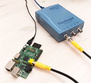
The Pi has a composite output, which seems like a standard RCA connector. Presumably it’s sending out a rather straightforward analog signal. Would it be possible to digitize this signal and emulate a composite video display on the PC?
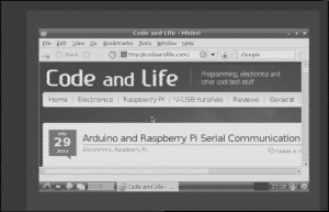
The short answer is: Yes. The medium length answer is, that it either requires an expensive oscilloscope with very large capture buffer (millions of samples), or then something that can stream the data fast enough so there’s enough samples per scanline to go by. Turns out my Picoscope 2204 can do the latter just enough – it isn’t enough for color, but here’s what I was able to achieve (hint: you may want to set video quality to 480p):
What my program does is essentially capture a run of 500 000 samples at 150ns intervals, analyze the data stream to see whether we have a working frame (and because the signal is interlaced, whether we got odd or even pixels), plot it on screen and get a new set of data. It essentially creates a “virtual composite input” for the PC. There’s some jitter and horizontal resolution lost due to capture rate and decoding algorithm limitations, and the picture is monochrome, but if you consider that realtime serial decoding is considered a nice feature in oscilloscopes, this does take things to a whole another level.
Read on to learn how this is achieved, and you’ll learn a thing or two about video signals! I’ve also included full source code (consider it alpha grade) for any readers with similar equipment in their hands.
Hardware needed for the hack

The magic is done in software, so on the hardware side things are quite simple:
- Composite video source (NTSC preferred, PAL might work straight away or with minor tweaks, Raspberry Pi can do both, NTSC is the default)
- RCA cable and ways to connect it to scope
- USB oscilloscope with C API which can capture at 5 MS/s for at least 250 000 samples
My Picoscope 2204 could achieve sampling interval of 150 ns (6.67 MS/s) without hanging during streaming, and I captured 500 000 samples in the final version. Earlier versions worked with slightly slower capture rate of 5 MS/s and a buffer of 250 000 samples (0.050 seconds) just fine. When the capture buffer length becomes less than two NTSC fields (at almost 60 fps it’s 0.033s), the decoding algorithm may not have enough data to work with.
Decoding the signal
Composite video signal from the Pi turned out to be rather oscilloscope-friendly: The RCA cable carries ground in the outer ring of the connector, and the “spike” inside the connector carries the signal. On my Pi, the voltage level of the signal was between 200 mV and 2 V, so the cable could be connected directly to the USB scope. If you try this yourself, use a multimeter first to verify that there will be no ground loops (i.e. grounds are at about same level). Here’s what the video signal looks like:
Each line is preceded by a “sync pulse” (horizontal sync) that takes the signal low for a short period. Then there’s a “colour burst” that could be used to calibrate color decoding, and finally the picture signal follows, starting with black reference level and ending back there. In the picture you can see one black horizontal line, followed by four additional lines with increasing amount of brighter pixels in the left side of the image. Here’s a closeup of one waveform, where you can also see the initial “colourburst” more clearly (before the actual image data and on slightly lower base voltage level):
The signal level at a given point denotes pixel luminosity, and the color is coded by modulating this “brightness level” signal with a high-frequency sine wave. However, the sampling rate would need to be much higher to correctly detect the phase and amplitude of this color signal, so we’ll just make do with the monochrome one this time.
A simple algorithm to transform this signal into pixels on screen is just to wait that the voltage rises above a predetermined treshold (I used 2048 which is probably about 205 mV), and then just treat each sample as a pixel brightness. Correct levels for black and white can either be pre-measured and supplied to the program, or deduced from signal – I used a naive approach to look for minimum and maximum voltages from first batch of sampled data (excluding the low sync pulses of course) and added manual controls to move the black point.
Vertical synchronization
With the above, we could already get a stream of horizontal lines to display, but we wouldn’t know where one frame ends and another begins. For that, we need to recognize the “vertical blanking” period from the signal. Here’s what it roughly looks like:
I had to do some head-scratching before I realized that the easiest way to recognize the start of VSYNC is just to see how long the “non-sync” portion is: normal scanlines are always at least twice as long as the first VSYNC signals. Here’s a closeup from the transition (two black scanlines followed by VSYNC):
Identifying odd and even fields
After I added support for the VSYNC signal, I already had a working prototype at my hands. See the initial program video at Youtube for an example. However, the picture was “twitchy” and quite small. I then realized the cause for this: both NTSC and PAL video signals are interlaced, with the even lines in one “field”, followed by VSYNC, and then the odd lines in another “field”. If only I could recognize which type of field I had just received from the scope, I could double the vertical resolution and remove the 1-pixel vertical twitching effect caused by random display of odd and even lines depending on which was decoded! I used Martin Hinner’s excellent page to understand it all a bit more.
Turns out both the PAL and NTSC encode the field synchronization information within the VSYNC signals. For even fields, VSYNC signal begins in the middle of a scanline, and for odd fields, after a complete scanline. By counting the half-long non-sync (i.e. above treshold) periods before longer sync (i.e. below treshold) periods in the VSYNC signal I could determine which was which – six before even lines, seven before odd lines.
You can get the source code and Makefile to try out the things yourself. I’ve also included Picoscope and SDL DLL files, as well as executables, so in case voltage levels work the same across different scopes, it might work just by double-clicking the con_ntsc.exe
Possibilities for future improvement
Due to limited capture rate, the horizontal resolution as well as alignment is currently less than perfect – individual lines are randomly displaced by 1-2 pixels, which causes readability issues with small text. A better capture rate, or alternatively algorithmic filtering (for example using data from multiple frames) could improve this.
Also, the code currently does not read two consecutive fields from the signal, so for example several odd fields can be decoded consecutively, causing the even fields “fall behind”. Capturing enough data for both fields with one go would solve this.
Furthermore, PAL decoding should be very similar to the NTSC one implemented here. Also, by analyzing capture data more carefully, the program could adjust many critical values to decoding by itself without manual intervention (black level, signal lengths, etc.). Finally, a decoder circuit could be used to separate color components from the signal so they could be digitized even with limited capture rate.


3 comments
ram sankar mohanty:
i want to project ‘real time video decoding with picoscope’ .how can get data .please give send my email and how can contact??
jokkebk:
In case you want to contact me privately, you can send e-mail to jokkebk at codeandlife.com. :)
an:
that was quite interesting, thank you for the write-up