Code and Life

Programming, electronics and other cool tech stuff

Supported by

Supported by Picotech

Raspberry Pi Serial Console With MAX3232CPE

In addition to the audio, video, network and USB connectors, the Raspberry Pi also has 26 GPIO pins. These pins also include an UART serial console, which can be used to log in to the Pi, and many other things. However, normal UART device communicate with -12V (logical “1”) and +12V (logical “0”), which may just fry something in the 3.3V Pi. Even “TTL level” serial at 5V runs the same risk.

So in this short tutorial, I’ll show you how to use a MAX3232CPE transceiver to safely convert the normal UART voltage levels to 3.3V accepted by Raspberry Pi, and connect to the Pi using Putty. This is what you’ll need:

  • Raspberry Pi unit
  • Serial port in your PC or USB to serial -adapter
  • MAX3232CPE or similar RS-232 to 3.3V logic level transceiver
  • 5 x 0.1 uF capacitors (I used plastic ones)
  • Jumper wires and breadboard
  • Some type of female-female adapter

The last item is needed to connect male-male jumper wires to RaspPi GPIO pins. I had a short 2×6 pin extension cable available and used that, but an IDE cable and other types ribbon cable work fine as well. Just make sure it doesn’t internally short any of the connections – use a multimeter if in doubt!

The connections on Pi side are rather straightforward. We’ll use the 3.3V pin for power – the draw should not exceed 50 mA, but this should not be an issue, since MAX3232CPE draws less than 1 mA and the capacitors are rather small. GND is also needed, and the two UART pins, TXD and RXD.

Using MAX3232CPE for 3.3V UART

The MAX3232CPE is very much like it’s 5V sister model, MAX232. It uses a few capacitors to deliver true +-12V RS-232 signalling on one end, and 3.3V signalling on the other. I’m not going to cover the internals in detail this time, please either refer to the datasheet or my previous tutorial discussing this same chip.

Above you can see one rather compact way to wire the MAX3232. The orange, white, green and black wires come from Raspberry Pi and provide power and data lines. The red, brown and blue wires go to the RS-232 port – see the illustration on right for connections on this side.

Update: The RS-232 connection diagram is from the side you’d solder the wires from (“back side” of the connector), and wired so you can connect a PC USB serial adapter to Raspberry Pi. If you’d like to talk to serial peripherals from Pi instead, RX/TX wires need to be reversed.

Before you connect the Pi, check with a voltmeter that GND from Raspberry Pi and GND from RS-232 do not differ from each other too much (a few millivolts is usually OK), otherwise you may risk a ground loop and damage to your equipment!

Using Putty to connect to Raspberry Pi

After you’ve made all the connections, double check the connections once more, maybe even check the this full sized photo. If everything looks OK, power up the Pi and plug in the RS-232 cable.

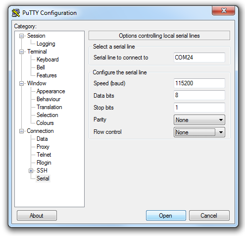
Now all you need to do is to fire up Putty, change connection type to “Serial”, enter your serial COM port, and then access the “Serial” settings (red highlight on the right image).

In the serial settings, make sure you have 8 bits, 1 stop bit, no parity and no flow control before you connect. I initially had XON/XOFF flow control and got nothing but garbage, so don’t forget this step!

Once the wiring and the settings are correct, you should be welcomed by the Raspberry Pi login screen (note that chances are the login text is already gone when you first connect, you’ll need to press enter a few times to get the login text again). Quite nice! Also, if you disable the login (Google for details), you can use the ttyAMA0 serial device for anything you like (for example, outputting logs or connecting to another device with RS-232 connection).

24 comments

Kaz:

I like the SP3232ECP/EEP (because it’s cheaper), and ICL3232CPZ (also because it’s cheaper). Both are pin-compatible to MAX3232CPE. They also sell USB-TTL adapters on eBay that are based on the PL2303 chipset – connect Tx/Rx/GND and you can access COM ports that way. Both are really handy :)

Steve Anderson:

I picked up one of these cheap on eBay for all my serial port needs:

http://www.sureelectronics.net/goods.php?id=1289

Makes hooking up pretty much anything with a serial port of any sort a breeze, from 3.3V electronics to a full RS-232 VFD display.

Andrei Hapenciuc:

Hi,

Raspberry PI is a great tool.
But it would be better if that micro USB would be a virtual com port, instead of having to use the UART and external hardware.

Does anyone has in plan to do this?

BR

Andrei

jokkebk:

Looks good. I only have a standard USB->RS-232 converter and need to do 5V and 3.3V TTL connectivity with MAX232/3232 chips. Doable but it does add an extra step..

Dave Bodnar:

I found an interesting board that does all of the work in connecting the Pi to a standard serial port. I have a description of the project on my web page, here:

http://www.trainelectronics.com/RaspberryPi/

thanks!

dave

David Wilson Clarke:

Just building one of these, on a bit of veroboard.

One point, you’ve wired the D9 as a DCE, would it not be more conventional to wire it as a DTE?

jokkebk:

The basic idea was to wire it so that I can connect to it from PC using a USB serial bridge. Of course if you’d primarily want to talk with serial peripherals instead of something that thinks of itself as DTE, you’d do it the other way around. I think.

I have to admit that every time that I think about device send, receive, MAX232 transmit/receive in/out, and the DB9 connectors which can be either viewed from solder side or connector side, and have their own RX/TX labeling and the DTE/DCE terminology, my brain nearly explodes. So I usually just end up walking it through in my mind once, writing down the instructions, and forgetting everything afterwards…

David Wilson Clarke:

Oh yes. I have to work it out from first principles each time, too. And sometimes just put a breakout box in, just to make sure each end is driving different pins. But here, presenting the connections as they would be on a PC seems the most logical, although here as you’re building it yourself, you can taylor it to what cables you have available.

Neville Bradley:

The micro USB on the PI is power only (no data lines) so it can never be used as a USB port unfortunately.

jokkebk:

Good point. I currently don’t have the time to remake the diagrams, but added a note in the text to help readers. Thanks for your input!

Art VK4GO:

Hi I just order this what you guys will that works with the Raspberry Pi ?

http://cgi.ebay.com.au/ws/eBayISAPI.dll?ViewItem&item=150917423064

Cheers from Australia

jokkebk:

Looks very much like the MAX3232ACPE but with RS-232 connector and everything. My guess is that it would work nicely with the Pi. You may want to ascertain that output level actually is 3.3V before wiring it to the Pi, of course (with a scope or maybe a multimeter, and at least by studying the data sheet).

Francis:

Hi,

And if i want connect paspi to a TTL 5v serial for example an arduino ?

Cheers of Paris

jokkebk:

See my two newer posts on Raspberry Pi, first uses a resistor-based voltage bridge (a bit doubtful as flashing Arduino will output 5V over Pi RX pin!), and the latter (Pi as Arduino HDMI shield) uses a safer level converter chip.

Bob Cochran:

Thank you, this post prompted me to order the MAX3232 chip, since I will want to do serial stuff on my device. I almost bought this breakout board from Sparkfun, https://www.sparkfun.com/products/11189? but it looks like only 10 of the 16 pins are broken out on the board, and I want all 16 pins.

Grinch:

Great, just a info. In what way you know that the COM port number was 24? Where you read this info?
Thanks in advance

jokkebk:

I went to Device Manager (e.g. right-click My Computer, select Properties, and there should be a link) and checked under COM ports, one can usually tell by a look which is the correct one. :)

ohoservices:

Thank you… Worked great for me.

Bartek:

I have nothing like garbage in Putty…
“▒3▒▒▒▒▒>▒▒▒▒▒|▒▒▒▒▒▒▒▒▒?▒▒▒▒▒▒8▒▒▒▒▒▒▒▒▒▒▒▒▒▒▒▒▒▒▒▒>?▒▒▒>▒▒▒▒▒z▒▒>▒▒▒▒▒▒▒▒▒▒▒▒▒▒{▒▒▒▒▒▒
▒▒▒▒~>▒▒▒ל▒▒▒▒▒▒▒▒▒▒~▒▒▒▒>▒▒▒▒▒Ξ▒▒▒▒▒▒▒▒휜▒q▒▒▒▒▒▒▒▒▒▒▒▒▒▒▒▒▒▒▒▒▒▒~▒▒▒▒▒▒▒▒▒▒

What should I do? It is perfectly done by your picture. I have SP3232ECP… 115200, 8 data bits, 1 stop bit, parity none, flow control OFF.

Joonas Pihlajamaa:

Sorry, can’t help you much there. If you have an oscilloscope or logic analyzer, you might want to see what is on the lines. Other idea is to try something else with either end, if you can get serial to work with RaspPi, you know the problem is likely related to the other end.

It’s possible also that the GPIO pin in RaspPi has been damaged by overvoltage (they only handle 3.3V) and sends random bits. Or the same on other end. Or some other program is interacting with same pins. Or the cable is broken. Or the conversion chip is faulty. Or differs from MAX. Or…

Bartek:

Yeah, my chip is propably damaged…

Raymond:

The USB-TTL PL2303 devices are excellent and terminate in a 5V interface. Is there a similar device that terminates in 3.3V interface? A chip could be used to translate 5V => 3V, however, in the case less is more.

computer_freak_8:

When I search for the Max3232CPE, all I can find are specs that say it’s a 5V shifter. Am I missing something?