Benchmarking Raspberry Pi GPIO Speed
UPDATE2: You may also want to check out my Raspberry 2 vs 1 GPIO benchmark!
UPDATED: 2015-02-15! This article has been very popular, so I’ve now updated all the benchmarks using the latest firmware and library versions. The scope has also been upgraded to a PicoScope 5444B with better resolution and bandwith than the earlier models. :)
Don’t try this at home! Shorting GND and VCC with a probe might fry your Pi and more!
Method and Summary of Results
The basic test setup was to toggle one of the GPIO pins between zero and one as fast as possible. GPIO 4 was selected due to easy access and no overlapping functionality. This is basically the “upper limit” for any signalling one can hope to achieve with the GPIO pins – real-life scenarios where processing needs to be done would need to aim for some fraction of these values. Here are the current results:
| Language | Library | Tested / version | Square wave |
|---|---|---|---|
| Shell | /proc/mem access | 2015-02-14 | 2.8 kHz |
| Shell / gpio utility | WiringPi gpio utility | 2015-02-15 / 2.25 | 40 Hz |
| Python | RPi.GPIO | 2015-02-15 / 0.5.10 | 70 kHz |
| Python | wiringpi2 bindings | 2015-02-15 / latest github | 28 kHz |
| Ruby | wiringpi bindings | 2015-02-15 / latest gem (1.1.0) | 21 kHz |
| C | Native library | 2015-02-15 / latest RaspPi wiki code | 22 MHz |
| C | BCM 2835 | 2015-02-15 / 1.38 | 5.4 MHz |
| C | wiringPi | 2015-02-15 / 2.25 | 4.1 – 4.6 MHz |
| Perl | BCM 2835 | 2015-02-15 / 1.9 | 48 kHz |
Shell script
The easiest way to manipulate the Pi GPIO pins is via console. Here’s a simple shell script to toggle the GPIO 4 as fast as possible (add sleep 1 after both to get a nice LED toggle test):
#!/bin/sh
echo "4" > /sys/class/gpio/export
echo "out" > /sys/class/gpio/gpio4/direction
while true
do
echo 1 > /sys/class/gpio/gpio4/value
echo 0 > /sys/class/gpio/gpio4/value
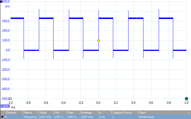
doneAs expected, the performance of this implementation is not good: A 2.9 kHz square wave can be generated using this method. For some reason, this figure has come down since 2012, when I measured 3.4 kHz. Might be a firmware update. For turnings things on and off this is enough, but no signalling and hardly even LED PWM is feasible.
Update: Note that I have my probes at 1:10 setting, so the actual voltage value is 10x what is displayed in the figures!
Shell with WiringPi gpio utility
WiringPi comes with the gpio command, but its performance is almost 100x slower (40 Hz) than the plain shell, possibly due to starting delay of the executable. Code is a bit cleaner, though:
#!/bin/sh

gpio mode 7 out

while true
do
        gpio write 7 1
        gpio write 7 0
done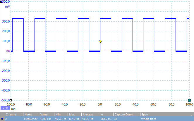
Python with RPi.GPIO
One of the simplest ways to access the GPIO with a “real programming language” (sorry bashers :) is with the RPi.GPIO Python library. Installing it was simple: Just download the .tar.gz file, extract files and run python setup.py install. Our test script is simple as well:
import RPi.GPIO as GPIO
GPIO.setmode(GPIO.BCM)
GPIO.setup(4, GPIO.OUT)
while True:
GPIO.output(4, True)
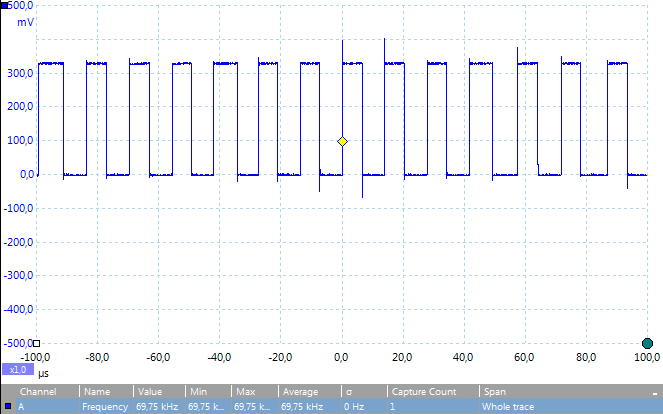
GPIO.output(4, False)The library performance has increased steadily. 0.2.0 was less than 1 kHz, but 0.3.0 already bumped this to 44 kHz. As of version 0.5.10, the rate has again increased, and is now around 70 kHz!
The improved performance in Python is probably enough for simple multiplexing and LED PWM applications. Note that the new version requires some additional steps in installation, name getting Python development kit with sudo apt-get install python-dev. I originally got errors while trying this, but upgrading my packages solved that problem.
Python with WiringPi2 bindings
Another alternative for Python are the wiringPi Python bindings. Installation requires cloning the respective version and apt-get installation of python-dev and python-setuptools.
I installed the newer WiringPi2-Python version. Earlier tests with older version 1 gave a 19.5 kHz square wave. New test version with wiringpi2 module has improved to 28 kHz:
import wiringpi2

io = wiringpi2.GPIO(wiringpi2.GPIO.WPI_MODE_PINS)

io.pinMode(7,io.OUTPUT)

while True:
    io.digitalWrite(7,io.HIGH)
    io.digitalWrite(7,io.LOW)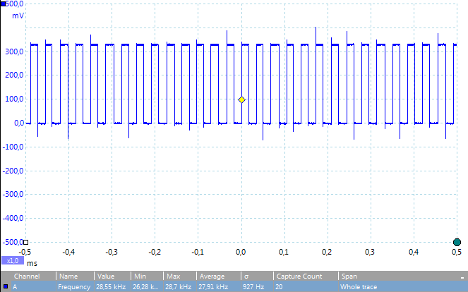
Ruby with WiringPi bindings
WiringPi also has Ruby bindings, which can easily be installed:
sudo apt-get install ruby-dev
sudo gem install wiringpi
Code is also very simple:
require 'wiringpi'

io = WiringPi::GPIO.new

while true do
        io.write(7,0)
        io.write(7,1)
end
Performance is about the same as Python version, around 21 kHz square wave is generated:
C: Maximum performance
The Raspberry Pi Wiki gives a nice C code example for true hardware-level access to the GPIO. The interfacing is slightly more difficult, but code isn’t too bad. I took the example program and simplified the main method after setup_io() to this:
// Set GPIO pin 4 to output
INP_GPIO(4); // must use INP_GPIO before we can use OUT_GPIO
OUT_GPIO(4);
while(1) {
GPIO_SET = 1<<4;
GPIO_CLR = 1<<4;
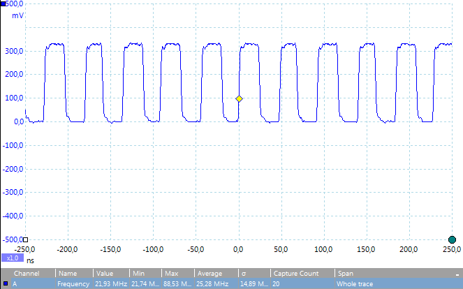
}Without any optimizations, I got an excellent 14 MHz square wave. Adding -O3 to the compile command (gcc -O3 strobe.c -o strobe) increases the rate to hefty 22 MHz. Measuring the waveform with oscilloscope starts to require VERY short wiring between probe and ground, otherwise it just looks like a sine wave due to capacitance in helper wires!
C with BCM2835 library
Mike McCauley has made a nice C library called bcm2835 that can also be used to interface with the GPIO pins using C. Its installation was also quite easy: download, run the standard configure / make / make install commands and you’re good to go. Compiling the code is done with the -lbcm2835 compiler flag to include the library. Benchmark code looked like this (note that in Broadcom numbering, GPIO 4 is P1_07):
#include <bcm2835.h>
#define PIN RPI_GPIO_P1_07 // GPIO 4
int main(int argc, char *argv[]) {
if(!bcm2835_init())
return 1;
// Set the pin to be an output
bcm2835_gpio_fsel(PIN, BCM2835_GPIO_FSEL_OUTP);
while(1) { // Blink
bcm2835_gpio_write(PIN, HIGH);
//delay(500);
bcm2835_gpio_write(PIN, LOW);
//delay(500);
}
return 0;
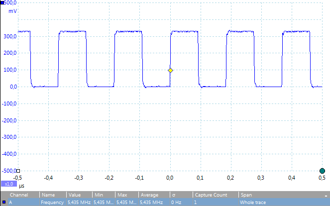
}The performance is not far beyond the earlier C example: A solid 5.4 MHz with the use of -O3 optimization flag. Definitely enough for most applications!
C with WiringPi
Gordon Henderson has written an Arduino-like wiringPi library using C. It’s a popular one and quite easy to use. Here’s the simple test program:
#include <wiringPi.h>

#include <stdio.h>
#include <stdlib.h>
#include <stdint.h>

int main() {
  if (wiringPiSetup () == -1)
    exit (1) ;

  pinMode(7, OUTPUT);

  while(1) {
    digitalWrite(7, 0);
    digitalWrite(7, 1);
  }

  return 0 ;
}
With the normal GPIO access method, the library already clocks an impressive 4.1 MHz square wave:
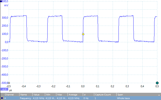
There’s also a GPIO access method which involves calling wiringPiSetupGpio() instead of wiringPiSetup(), and using the normal GPIO numbering instead of wiringPi native renumbering system, so 7 becomes 4 in the above code. The performance is increased slightly to 4.6 MHz:
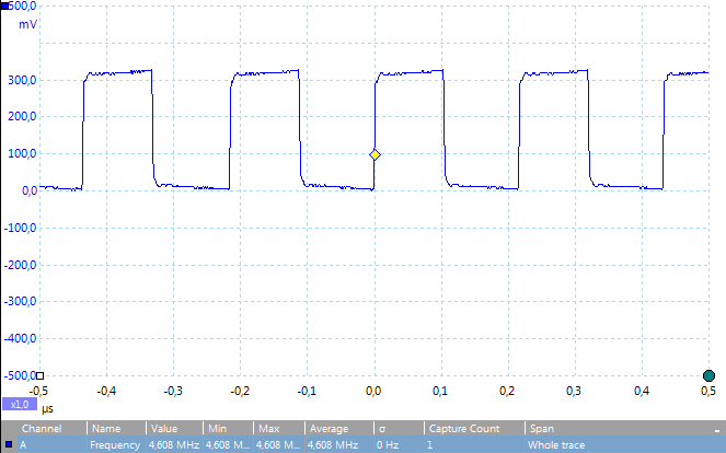
Since 2012, the WiringPi performance has somewhat decreased, as I originally got 7.1 MHz from the GPIO access method. This might of course also be due to firmware changes (I am running the tests over multitasking OS in a SSH shell, after all).
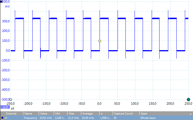
Also, a /proc/sys based access method was provided, but it was a lot slower, running at 120 kHz on average (200 kHz). The wiringPi library also has Python, Ruby and Perl bindings. See above for the Python version performance, I’d expect the Perl and Ruby bindings to be on the same speed level.
Perl with BCM2835.pm
Mike McCauley has also made a Perl module that uses the above C library to provide GPIO access in our favorite language (who doesn’t love Perl?). For installation, I recommend skipping cpan command and searching for the latest version from CPAN, downloading the .tar.gz with wget, extracting, and running perl Makefile.PL / make / make install commands. Like it usually is, the Perl code isn’t pretty, but it does the job well:
use Device::BCM2835;
use strict;

Device::BCM2835::init() || die "Could not init library";

# Set RPi pin P1_07 (GPIO 4) to be an output
Device::BCM2835::gpio_fsel(&Device::BCM2835::RPI_GPIO_P1_07,
                            &Device::BCM2835::BCM2835_GPIO_FSEL_OUTP);

while (1) { # Strobe
    Device::BCM2835::gpio_write(&Device::BCM2835::RPI_GPIO_P1_07, 1);
    Device::BCM2835::gpio_write(&Device::BCM2835::RPI_GPIO_P1_07, 0);
}
Compared to the Python version, the Perl module packs a bit more punch: 48 kHz square wave was achieved – enough for some PWM applications, if not quite enough for audio generation etc.
As with the Python version, any tips to improve Perl execution performance are welcome! Interestingly enough, the 1.0 version achieved slightly better performance than the latest 1.9 version – around 59 kHz. The difference isn’t large enough to not upgrade, though.
Conclusion
Based on these simple benchmarks, I can conclude that shell is only usable for simple automation tasks etc., but at least Python/Ruby/Perl is needed for anything more complex such as LED PWM. Python with RPi.GPIO is the fastest of these, but Perl with BCM 2835 bindings comes close. For actual signalling applications, C seems like the only choice. I haven’t tried the C# and Java interfaces, but I’d expect them to be on the level of C and Perl, respectively, or a bit slower.
What is not evident from the snapshots, however, is that due to multitasking nature of Linux, the GPIO manipulation is constantly interrupted for short periods when the CPU is doing something else, such as receiving or sending data over network, writing log files, etc. Only a realtime OS is suitable for timing-critical stuff, or using the hardware level support for I2C, UART and such. A good alternative is an independent add-on board with a microcontroller, such as Arduino or several other alternatives. Communicating over UART is simple with such devices.