
3.3V UART with MAX3232CPE
Wed, Apr 11, 2012 in post Electronics ATtiny2313 max232 max3232 max3232cpe rs-232 uart usart
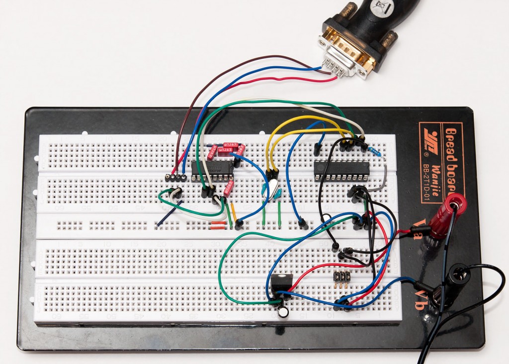
Before diving right into SPI communications for my SD tutorial, I wanted to have a 3.3V development platform that could output some meaningful status information, not just light a LED if something goes wrong. In this post, I will outline the basic testing platform that will be used in the upcoming part 3 of that tutorial, and discuss a little about UART on AVR in the progress. Here’s what we’ll build:

If you want to build it yourself, you’ll need:
- ATtiny2313 or other AVR chip with UART pins (RX/TX) separate from SPI pins (MOSI/MISO/SCK)
- 20 MHz crystal (other speeds will work, too) and ~27 pF capacitors
- 4k7 pullup resistor for ATtiny2313 RESET pin
- 3.3V regulator such as LD1086V33 or some other 3.3V voltage source
- 2 filtering caps for the regulator input/output sides, 10 uF
- MAX3232CPE or similar RS-232 transceiver that works on a 3.3V voltage
- RS-232 port on your computer or a USB to RS-232 dongle
- RS-232 to breadboard connector (home-soldered example seen above)
Crystal can be left out if the internal oscillator is calibrated accurately enough for RS-232 timings (less than 1 % error). Also, you can build this setup with a 5V voltage source and normal MAX232, but that combination cannot communicate directly with an SD card using level conversion.
A Word on Wiring

I assume that you have prior experience on wiring a 6-pin programming header to a ATtiny2313 and know the basics of regulators. If in doubt, you can refer to my USB tutorial part 1 which covers the 3.3V regulator covered here in more detail. Here’s one good order to do this:
- Start by wiring >5V voltage source to regulator inputs. Add a filtering cap between the VIN and GND.
- Connect regulator output (green wire in my setup) to breadboard VCC power rail, and GND to GND. Add another filtering cap there between VCC and GND.
- Turn on power for a moment to confirm with a multimeter that you have 3.3V at power rails
- Wire the ATtiny2313 with power and RESET pullup, then wire the 6-pin programming header
- Connect a programmer and check that the chip responds
- Add a crystal and 27 pF caps on both sides connected to ground. Wire the crystal to ATtiny2313 XTAL pins
- Update fuses – for ATtiny2313 the 20 MHz crystal the low fuse should be FE
- You could flash a simple LED blinker at this point to see if the crystal is working OK
RS-232 with MAX3232CPE
The MAX232 and it’s pin-compatible 3V version, MAX3232 is basically a nice level shifting circuit designed to convert the +-12V lines from RS-232 into TTL-compatible 5V (232) or 3.0-5.5V (3232) levels. To reach the higher (and lower) voltages, it uses charge pumps and four 0.1 uF (standard MAX232 needs 1.0 uF) capacitors, plus one more for VCC stabilization. Here’s the pinout and logical diagram:

So basically we put a capacitor between C1+ and C1-, another between C2+ and C2-, third between VS+ and ground, fourth between VS- and ground, and finally the fifth between VCC and ground. We will only be using one of the two transceivers, so pins 7, 8, 9 and 10 are not connected. The TX and RX are wired as follows:
- ATtiny TXD (pin 3, green jumper wire) is wired to T1IN (pin 11)
- ATtiny RXD (pin 2, white jumper wire) is wired to R1OUT (pin 12)
- RS-232 “Receive” (pin 2, the red wire) is wired to T1OUT (with a green jumper wire)
- RS-232 “Transmit” (pin 3, the brown wire) is wired to R1IN (with a white jumper wire)
This is consistent with the following logic: ATtiny is wired to “TTL/CMOS” side of MAX3232, i.e. to T1IN and R1OUT (right schematic above), and RS-232 to the other side, T1OUT and R1IN, respectively. The ATtiny “TX” and “RX” correspond to MAX3232 T/R lettering, but the RS-232 does not – you can think the RS-232 “Receive” pin (pin 2) as computer’s way of saying “I will receive data from this pin” and “Transmit” pin as “I will transmit data from this pin”. In other words, “Receive” means “Transmit into this” and “Transmit” means “Receive from here”. Confusing, isn’t it?
In any case, after you’ve read the above two times, consult the big picture above again to verify that you got it correctly, and proceed to the code part. :)
UART code in AVR
The ATtiny2313 datasheet section on UART (or “USART”, as they like to call it) is surprisingly clear – it even contains example code on using it. Here’s a simple test program that just echoes back everything that is sent over the RS-232:
#include <avr/io.h>

void USARTInit(unsigned int ubrr_value) { // is UBRR>255 supported?
    //Set Baud rate
    UBRRH = (unsigned char)(ubrr_value >> 8);
    UBRRL = (unsigned char)(ubrr_value & 255);
    // Frame Format: asynchronous, no parity, 1 stop bit, char size 8
    UCSRC = (1 << UCSZ1) | (1 << UCSZ0);
    //Enable The receiver and transmitter
    UCSRB = (1 << RXEN) | (1 << TXEN);
}

char USARTReadChar() { // blocking
    while(!(UCSRA & (1<<RXC))) {}
    return UDR;
}

void USARTWriteChar(char data) { // blocking
    while(!(UCSRA & (1<<UDRE))) {}
    UDR=data;
}

int main() {
    USARTInit(64); // 20 MHz / (16 * 19200 baud) - 1 = 64.104x

    while(1)
        USARTWriteChar(USARTReadChar()); // echo

    return 1;
}

Note that the “UBRR magic constant” 64 is correct for a 20 MHz crystal and baud rate of 19 200. Use the formula (int)(F_CPU / (16 * baudrate)) to calculate other alternatives. Note that the rounding error should not exceed 1-2 % or it will not work, so all bit rates might not work well with your particular crystal.
Compile and flash it to chip, and provided that you have installed your RS-232 drivers on PC, you should be able to use Putty or some other terminal to connect. Note that pressing
Now that we’ve got everything working, it would be easy to modify the code to not just echo everything back, but perhaps rot-13 encrypt everything, or do some other creative thing. But that’s it for me today, it’s past midnight and I’m getting some sleep now.
8 comments
Hesham Yusuf:
Is it possible to use MAX3232CPE as an interface between 3.0V and 5.0V devices. i.e. can it change 3.0V to 5.0V and 3.0V to 5.0V? (TX, RX)
jokkebk:
Hmm, I’m not sure, I think the MAX3232 will normally boost the RS-232 levels to +-10V, you’d need to know exactly how the capacitors are used to boost the regulator to get anything tolerated by 5V devices.
Of course, you could use MAX3232 on the 3V end and MAX232 on the 5V end, but that’s quite wasteful and also slow. You’ll be much better of with a quad/hex buffer for level conversion – see my level conversion post for details.
Actually, if you have two MCUs that need to talk to each other, in many cases you could just connect the TX pin of the 3V device straight to 5V RX, most circuits will interpret something like 3.3V as logic 1. The 5V TX pin can be connected directly to 3V RX if the pins are 5V tolerant, but even if they are not, a simple voltage divider using two resistors would be enough and probably faster than the MAX(3)232 method.
Kaiwan:
Hi,
Thanks for this useful post!
Am attempting to replicate this in order to get serial console o/p from my R Pi to my laptop. Did not work on first attempt though the connections seem correct.
A silly qs perhaps: your circuit/logic diag for the MAX232CPE shows a few capacitors (0.1uF) being used with a specific *polarity*; so what type caps are these? tantalum capacitors?
TIA!
Kaiwan.
jokkebk:
Yeah it seems I’ve drawn them with polarity. I’ve used tantalun caps with MAX232 without issues, and with 3232 I actually used plastic caps. I bet both work great. Electrolytes I haven’t tried yet.
Hope you get your project working!
Kaiwan:
Hey jokkebk,
It worked! Thanks v much..
Actually, it all worked once i used tantalum capacitors with polarity as shown in your diagram; did seem to make a difference!
Thx again.
daniel demus:
The charges input to the capacitor determine the polarity, not the cap. The area of the plates determine the maximum charge the cap can hold (the number of molecules.) A cap is nothing more than two plates separated by paper. Am I missing something? Please enlighten me.
Joonas Pihlajamaa:
Tantalum caps definitely have a polarity, I’ve blown one having it the wrong way – the fumes are probably not too good for one’s health. I think plastic ones can be put either way, it depends on the structure of the cap.
Joonas Pihlajamaa:
You are right, the circuit diagram is from a datasheet and most definitely positive/negative is defined by the circuit they are used in. The point I was making in the above conversation was just that some capacitors don’t care which way they are inserted, others (like electrolyte and tantalum) do and for those you need to be careful how you insert them.
Wikipedia will likely tell why, but electrolyte caps cannot tolerate high reverse voltages without breaking down (or exploding violently). Something to do with the structure.