Logic analysis with Bus Pirate
Sat, May 5, 2012 in post Electronics Reviews bus pirate logic analyzer rxtx sd spi sump
While preparing for my SD tutorial, I realized it would be a long, uphill battle to debug SPI communications with a two-channel oscilloscope, especially when I had no prior experience on implementing SPI with AVR. To break the learning curve to manageable steps, I decided to get a Bus Pirate, a serial protocol tool I had heard a lot of good things about. What made the decision even easier was the fact that my local electronics supplier had just started selling the SparkFun version of Bus Pirate.
In this compact post, I’ll discuss my first impressions of the Bus Pirate, and try out the logic analyzer functionality.
Bus Pirate General Impressions
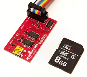
The first thought that crossed my mind when I saw the Bus Pirate in real life was how small the device was. As you can see, it’s hardly larger than an SD card. All the components are of surface mount type, LEDs included. USB cable was not included but fortunately I had several in my cable drawer. The thing does not need any other setup than plugging it in and installing the FTDI virtual COM port drivers. After that, it showed up as COM19 and I could connect to it with Putty. See the Bus Pirate 101 tutorial for installation details.
The v3 hardware is based on a PIC chip running at 3.3 volts and it took me a while to get comfortable with the power supply & pullup resistor logic – basically you can either use the Bus Pirate pins “normally” so an output pin is driven by the PIC, or in “open drain” mode, where a CD4066B analog switch connects the lines via pullup resistors to whatever is wired to the Vpu pin. This way, the Bus Pirate can interface with other than 3.3V devices (the PIC only pulls the line down or “lets it go” and the pullup takes the line high).
After poking around a bit, I proceeded to test communications with an SD card using Nada Labs’ excellent Bus Pirate SD tutorial. Everything worked right away, and the Bus Pirate immediately showed its worth, as the tutorial included all SD interfacing commands I would later need for my SD tutorial! I also did a little testing on the AVR SPI slave mode with Bus Pirate, sending commands from the pirate to a ATtiny2313 chip that I had (supposedly at that point) programmed to act as an SPI slave. That also worked nicely.
Unfortunately, the Bus Pirate does not work very well as SPI slave, so I couldn’t test my AVR SPI master code very well with it. The second drawback in a sense is that the Bus Pirate is really meant for “human interface device to serial protocols”, so it’s uses at high speed or automated serial communications is rather limited. It does have scripting support, but doing complex, high-speed serial interfacing is better left to a microcontroller running dedicated firmware.
Logic Analyzer Mode
A nice plus on the already-capable Bus Pirate is the SUMP-compatible logic analyzer mode. The Bus Pirate automatically recognizes when the SUMP logic analyzer software tries to communicate with it, so everything kinda works “out-of-the-box” once you have the software installed.
Speaking about the software, it is quite a nuisance to install on a 64-bit Windows computer. It relies on the RxTx serial library for communications, and to install that, you need to locate your Java Run Time Environment (JRE) directory and place the .jar file to jre/lib/ext and .dll files to jre/bin. I had four different JREs installed, and once I had removed the older ones to help me locate the correct one, it turned out that only 32-bit JREs are supported. After installing a 32-bit JRE 1.7 and adding RxTx, I was finally able to run SUMP.
Once the program ran, it was easy to follow the steps outlined in Bus Pirate logic analyzer mode wiki page. As a first task, I decided to visually verify what I had experienced and known for a while: microswitches and buttons flicker between on and off when pressed or released. I wired a microswitch between ground and a breadboard strip, and added a pullup resistor to VCC to keep the line high until the switch is pressed. I then attached the MISO line (channel 1) of Bus Pirate to the same strip, set capture speed to 10 kHz, added a trigger on channel 1 and started capturing:

From the above image you can see that when I press down a microswitch, it first goes down momentarily, then goes back up again, and repeats the same until it the line finally settles to a LOW state. When writing any code for a microcontroller that needs to react to events where user presses a button, you need to take the above characteristic into account. Consider the following code:
// Wait for three clicks on PB0 and then continue
for(i=0; i<3; i++) {
  while(PINB & (1<
`
The above code does not work, because one click will seem like a dozen button presses to that code because of the "flicker". But if we add a 5 ms delay between the while loops, it starts working, because the flicker only lasts for a brief period.
Analyzing SD Card SPI Traffic
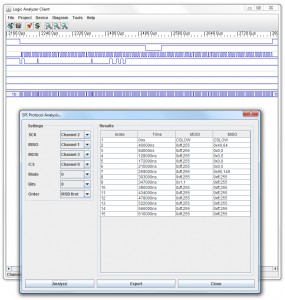
I also wanted to see if I could now actually view the SPI communications that were taking place with my SD card reading circuit and the SD card. So I wired the Bus Pirate to my SD tutorial project, set the capture rate to 1 MHz. One problem became immediately apparent: When triggering based on the SPI traffic, the 4 kB capture buffer could only hold the "80 empty clock cycles" before SD card initialization. I needed to connect an additional ATmega88 pin to Bus Pirate AUX (channel 4) and toggle that in the MCU firmware to "manually" start capturing. That did work nicely and I was able to capture the full waveform of the SD card initialization command (0x40) and the SD card response (0x01).
At this point, it also became rather apparent that my Bus Pirate and the SUMP logic analyzer had some difficulties communicating: I would randomly get "Could not communicate with device" errors when trying to capture waveforms, and at other times, the triggers did not seem to work, or the capture did not start for some other reason. Also, the SUMP interface does not do zooming with mouse, so after a while it became tedious to scroll back to the waveform whenever I switched the zoom ratio.
Also, the SPI traffic capture only succeeded with the 500 kHz and 1 MHz capture rate (maximum of Bus Pirate), which made for 5-10 ms worth of captured data - not much considering that there are delays of that magnitude between SD commands. Without run length encoding or repeated capture modes, the capabilities of this SW/HW combo is quite limited for logic analysis. However, it's much more than nothing!
Parting Thoughts
Based on the testing here, the Bus Pirate is a capable "starting point" type of tool for new projects that utilize serial communications some way. Also, its logic analyzer mode, while limited, is at least on par with my 2-channel PicoScope (although not on reliability front). A purchase definitely worth its price!
I'm currently trying to decide between building a simple ATmega88-based logic analyzer chip, buying a Open Source Logic Analyzer or getting a general-purpose ARM Cortex M3 or a Xilinx Spartan 3 based FPGA development board. If you have any good hardware suggestions on this area, please add a comment or e-mail me!
`


1 comments
Karel:
Nice review. I think the most value from the bus pirate to me is the direct communications with SPI and I2C commandline..
For logic analysis i use the scanalogic-2 (http://www.ikalogic.com/ikalogic-products/scanalogic-2/). It is fast, accurate and cheap.
Karel