Using Arduino Uno as ISP
Wed, Mar 21, 2012 in post Electronics Arduino arduino uno ATtiny isp programmer usb
One exciting piece of hardware I received with my Digikey order was an Arduino Uno board (R3). There was conflicting information whether or not it could be used as an ISP (in-system programmer), so I decided to see for myself. It turned out that with just one tweak, I could use the $26 device to program my AVR chips, essentially eliminating the need for a separate ISP such as $22 USBtiny!
This is obviously good news for any beginner with a budget, so I decided to write a short tutorial on how to do it. I used my USB password generator as a guinea pig for this project, so if you have wanted to try that out, this post also doubles as tutorial on how to build it on breadboard (good idea in any case before soldering it anywhere). Read on for details!
Minimal circuit for AVR-powered USB
For this exact project, you’ll need the following components (of course you can also build something else, as long as the Arduino can power it):
- ATtiny45/85 (the 20PU version, not the low-voltage one)
- 2 resistors, 68 ohm
- 2 pullup resistors, 2k2 and 4k7 ohms
- USB connector (instructions how to build it)
- Breadboard and wire
- 2 zener diodes, 3V6, 0.25W (too much watts and it might not work)
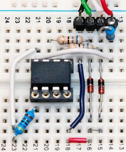
If you’re really cheap, you could probably use just one pullup, wiring it to RESET while programming and then to D+ after you’re ready. Click the image for larger version, here’s the schematic if you need it.
Update: As Ross McKenzie pointed out in the comments, 0.1 uF capacitor between VCC and GND should also be included. It seems to work without it most of the time, but it would be safer to have one there (to ensure the AVR chip being programmed gets a steady supply of power).
Wiring the Uno for Programming
If you haven’t flashed AVR chips before, it might be useful to know that the method used here is called serial programming with 6 pin interface. With dedicated ISP programmers you have the option to power the chip yourself (for example from external 3.3V source), but with Arduino as ISP, the safest bet is to power the chip from Arduino 5V and GND power connections.
In addition to powering the chip, you should know where the MOSI, MISO and SCK pins are in your microcontroller of choice. You can find this information from very beginning of Atmel’s datasheets, along with rather clear instructions for how to power the chip (for ATtiny45/85 we only need VCC and GND but some ATmegas for example have multiple VCC/GND pins that need to be connected as well as the AVCC pin). Here’s the pinout of ATtiny45/85 for reference:
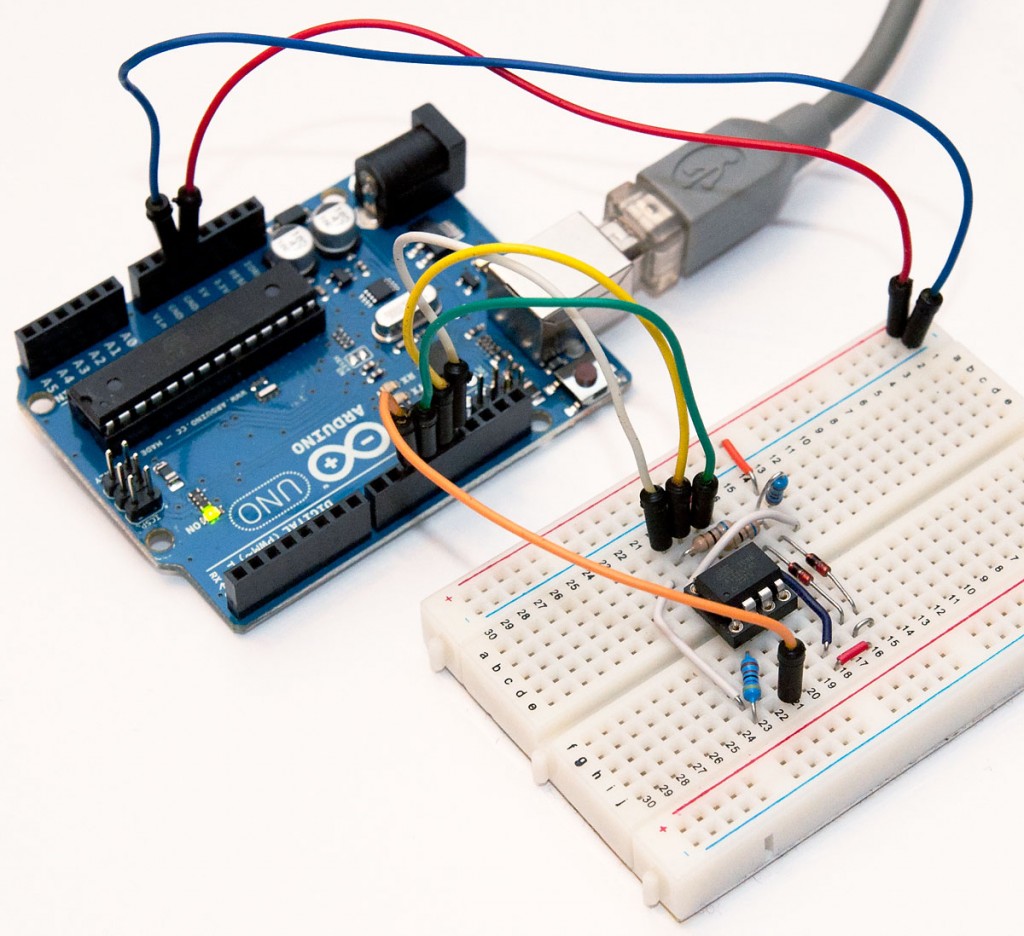
Here are the connections you need to make – note that because Arduino is already supplying 5V, I have detached the USB connector and used two jumper wires from the power rail to the breadboard rows 14 (VCC) and 17 (GND, behind the green wire). This is because the USB connector seemed to provide slightly higher voltage than the Arduino (about 0.1V more), and I thought it would be safest not to wire both at the same time, as current flowing from USB to Arduino circuit may not be such a good idea.
Arduino pin | Circuit pin | Explanation |
---|---|---|
5V, red | VCC | Used to power the chip during programming with same voltage as the programmer |
GND, blue | GND | Common ground |
10, orange | RESET | This line is pulled LOW to start programming |
11, green | MOSI | “Master out, slave in” – used for data from Arduino to chip |
12, yellow | MISO | “Master in, slave out” – used for data from chip to Arduino |
13, white | SCK | “System clock” – used synchronize the (SPI) data communications |
Programming
Once everything is wired up, you only need to upload the ArduinoISP sketch to your Arduino. If you’re running the 1.0 version of the Arduino IDE, there was some kind of timing/serial buffer/library mismatch and you need to tweak heartbeat()
function to reduce the delay(40);
to delay(20);
. I don’t exactly know the cause for this, but some sources talked about buffer issues and it just might be that a shorter delay avoids filling some transmission buffer. Older 0022 version worked “out of the box”.
After flashing, your ‘duino should work as avrisp-compatible programmer for avrdude (and most likely also AVR Studio):
avrdude -P com18 -b 19200 -c avrisp -p attiny45 -U flash:w:main.hex
I’ve updated the USB password project zip to also contain a Makefile.uno that uses the Uno as a programmer. Furthermore, to help updating the fuses I added a new build target “fuse”. So once you’ve got everything wired up, just go to the directory and type the following commands to update fuses and flash the USB password firmware:
make -f Makefile.uno flash make -f Makefile.uno fuse
That’s it! You are now equipped to flash any 8-bit AVR chip, anywhere, anytime (provided you carry your Arduino around, of course) with firmware of your choice.
Where next + sponsor appreciation
Thanks for reading! I’d also like to remind all readers, that if you have a topic in mind you’d like me to cover, I’m taking suggestions via comments and e-mail (jokkebk at codeandlife.com). I’ll also take this opportunity to thank Martin, for the first donation supporting this blog. I really appreciate it! I already spent the donation on parts for project I’m hoping to cover here in the future. :)
24 comments
Rik:
@jokkebk I should give you some update regarding my progresses.
First of all, I realized that instead of using a special programmer, I could use the Ardino… And that is what I actually did.
After some troubles, I managed to use avrdude with it and I was able to load the program on the attiny85 by using the Makefile.uno that you provided with the zip file (flash and fuse both ok).
On my mac, I see that it detects the presence of another keyboard but as you pointed out, it does’t work.
On my windows 7 PC, when I plug it in, I see that the attiny is recognized as a keyboard with the name passgen but then nothing happens. I don’t see anything automatically written when I plug it in at the login screen or while keeping no matter which text editor open.
Any idea???
Indeed thanks for the post for the arduino option!
jokkebk:
@rik: Nice to hear that using Arduino worked!
The problem on PC sounds like the keyboard doesn’t receive LED status updates. If you built it on a breadboard, you could try adding a LED and toggle it in different parts of code to see what parts of it get executed…
Rik:
@jokkebk: that’s a good plan, I will try that. Just one question: now I am uploading the main.hex file that you included in the zip file. In order to add a led somewhere in the code, I guess I have to edit the main.c file. Which command should I than use to compile it? Is there a special syntax or compiler?
I’ll keep you posted.
jokkebk:
With the makefile you should be able to just go into the directory and use “make flash” to update it. You can see all the commands the makefile then executes.
Oh, and double-check your fuse settings, too!
FLAR:
Hello jokkebk,
run this of the Arduino Duemilanove (ATMEGA328)?
thanks for answer
flar
FLAR:
“http://hlt.media.mit.edu/?p=1229”
jokkebk:
It will probably run great with Duemilanove, I think the Uno’s were the ones which had problems with the ArduinoISP sketch. :)
And thanks for the link, seems like someone has done almost the exactly same tutorial as me :)
Song Toàn:
It worked. I did get error initially. Then I tried -F. few times and it went success! Thanks a lot!
Ronald:
Hi, thanks for sharing the info, I have a (n00b) question, what diodes are you using? Thanks :)
jokkebk:
Good question, I seemed to have forgotten the zener diode ratings completely. 3V6 and not too big, I’ve used 0.25W ones but 0.5W might also work. Some people have had problems with 1W ones not conducting because they need more current..
Ed:
Probably extremely stupid of me ut what does the ‘makefile.uno’ exactly do? I have used an Arduino nano in the past to program hex files on an attiny and I never felt the need for a ‘makefile.nano’
Hunter:
Hey…
Just wondering if anyone has designed a PCB shield for this style of ISP. Want to not eat up a breadboard on something that I am just going to use often enough. Let me know, thanks in advance.
jokkebk:
It is a version of the makefile that has “-p arduino” in avrdude parameters instead of “-p usbtiny”. If you don’t use the makefile to run avrdude commands for you, you of course don’t need it. I just named the makefile .uno so I could keep the default makefile (without extension) separate.
In case you don’t work with makefiles: Think of it as a batch file (.bat) that runs several commands when you use the “make” command. The .uno is just another makefile with the avrdude programmer parameter changed.
jokkebk:
What part you’d like to have as a shield? Arduino shield? That would be a nice idea, and probably easy to solder up with 3×2 pin header, “empty” Arduino shield and some wire and solder.
Also, you could just use two pin headers for the 4 and 2 Arduino connections and solder a ribbon cable directly to them, eliminating the need for a shield.
If you meant ATtiny85 breadboardheader with an ISP header, there are probably some designs in the net. My ATtiny2313 header could serve as a basis for a new one, too. :)
Hunter:
The ISP portion as an Arduino shield, to put on top of an Uno. Once I get this design to work on a breadboard, I plan on designing and etch a shield board, just to make it easier to work with. Ideally, it will have the 3×2 header pin and a ZIF socket on it. But after I get this working on programming AVRs on a breadboard. Right now, avrdude is giving me a ‘Yikes! Invalid device signature.’ error, stating that the device signature is ‘0x000000’. Not certain if that is a Linux or timing related issue.
Ross McKenzie:
Hi jokkebk,
A mistake made by “virtually everyone” in using this method is the omission of the mandatory 0.1uF cap across the target chip’s power pins … including your good self.
Cheers,
Ross
jokkebk:
Is it actually part of Atmel’s recommended ISP programming setup, or just related to powering the AVR chips properly?
But you are right, it probably should have one there, I’ll add a note to the article. However, it seems to work fine without it (I’ve never had problems without the cap), even if it’s not the recommended way to do it.
Ross McKenzie:
It is not peculiar to the programming phase. It is required in all real world applications where the power supply is at some distance from the device(s) consuming or causing the pulse of energy.
Codongolev:
I know this is probably a dull question, but I’m new and I’m trying to learn, so here it goes. what are the diodes and 68 ohm resistors for? (I was able to research the pullup resistors, so I’m aware of what those do now.)
anonimous:
http://arduino.biz.ua/post/2013-02-11.html
russian article arduino mega as isp to atmega8
Tecnocroco:
hi!
that’s my question:
The schematic for the attiny85 (http://codeandlife.com/wp-content/uploads/2012/03/schematic.png), is for promgramming the attiny or is the minimal working circuit for the attiny?
Thanks!
P.D: I’m from Spain, so help me finding grammar mistakes!
Joonas Pihlajamaa:
It’s a minimalistic circuit for doing USB with ATtiny, for programming you would only need VCC, GND and maybe a weak reset pullup (e.g. 10k, and even the pullup isn’t usually needed), plus the ISP wires.
Grammar comments (as you asked :) — “This is my question” is better, and “is _it_ for programming” and similarily “or is _it_ the minimal…”. Otherwise seems very good. :)
Tecnocroco:
thanks you very much!
W. Wiedner:
There is also another good tutorial titled:
“Arduino Uno R3 as a true ISP programmer for any Attiny and Atmega AVR”
see:
– http://forum.arduino.cc/index.php?topic=317138.0
– https://app.box.com/s/ol1z8jjnrpy6wly4w61imt7wcbxk3fcg