$5 USB MIDI adapter with ATmega32u4
This article will detail how to build a USB MIDI adapter (one-directional: you connect the adapter with USB cable to your computer, and it receives notes and pedal data from your keyboard’s MIDI OUT and transmits them to your computer) with ATmega32u4, 6N137 optocoupler, a few resistors and spare MIDI connector or cable. Read on for details!
Preamble
Last year I wrote how you can turn Teensy LC into an inexpensive USB MIDI adapter. I used it to replace a non-working Chinese MIDI-USB adapter that did not send controller messages (i.e. piano pedal) properly to PC.
However, since the Teensy still costs $12, and you have to get some additional components, it doesn’t make sense to use it in a dedicated MIDI adapter, since you can get a working USB MIDI adapter for around $15 from Thomann and probably many other places.
But how about other boards? After making my Teensy LC adapter, I actually tinkered with Adafruit Pro Trinket, and got that working as well (the standard Trinket does not have hardware UART so V-USB and software UART is somewhat risky). But there is even a better board for this: The ATmega32u4 board I previously showed how it can be made into USB HID mouse. Let’s see how to turn it into a USB MIDI adapter!
Required hardware
To build this, you will need roughly $5.40 worth of components:
- SparkFun Pro Micro (clones with ATmega32u4 can be had for $3.50 from AliExpress, eBay, etc.)
- 6N137 optocoupler, which can be had for ~$0.30 a piece (I suggest sourcing a couple in case you burn one by accident)
- 330 ohm and 2 kohm resistors ($0.10) and 1N4148 diode if you want to be safe
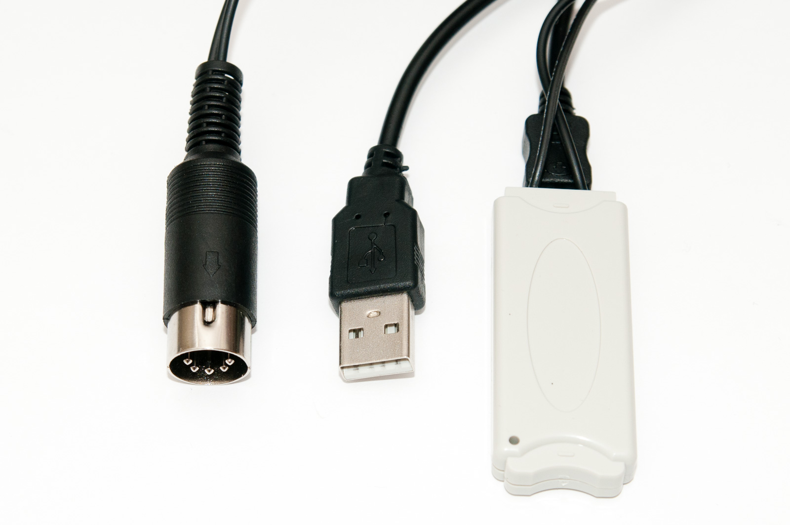
- MIDI connector or alternatively you can just cut a short cheap MIDI cable and wire it to your project, let’s say $1.50
If you’re like me and ended up with one of those trash $4 USB MIDI adapters, you can just sacrifice it and get two good MIDI connector cables “for free” if nothing else.
NOTE! This article will not cover how to solder a connector to MIDI cable wires, or how to test which pin is which using a multimeter or any other electronics 101 stuff. Also, I’m assuming you can connect jumper wires or solder them if you’re making a permanent circuit (in the latter case I still recommend starting with breadboard prototype first to make sure everything works).
Software primer
I’m using the amazing LUFA library to handle most of the firmware magic. Before doing the MIDI connector and optocoupler part, I recommend first flashing a simple USB MIDI test program to your ATmega32u4. Here’s what you need:
- Download the latest version of LUFA (I used LUFA 170418)
- Go to
Demos\Device\ClassDriversubfolder, and make a copy of theMIDIdemo directory. Let’s name itATmega32u4_miditest. - Replace the
midi.c,midi.h, andmakefilefiles with the ones from ATmega32u4_miditest.zip - Open a command prompt and go to this new directory
- Run
maketo compile the project - Plug in your ATmega32u4 board. Short the RST and GND pins (I usually just connect an IC test hook into RST and briefly touch GND with the jumper pin end) to reset the board (it will now wait flashing)
- Run
make avrdudeto flash the firmware.
You’ll need AVR-GCC and avrdude installed for the above to work. If you are unfamiliar with using these tools (including the command line), please google around and find the solution yourself instead of using the comments section for these questions!
The makefile in my zip and the build process is very similar to my previous LUFA mouse article so you might want to check that out to find out more. Here’s the beef of midi.c:
#define BUTTON PD2
#define BUTTONPIN PIND
#define BUTTONPORT PORTD

int main() {
    uint16_t debounce = 0;
    uint8_t keydown = 0;

    /* Disable watchdog if enabled by bootloader/fuses */
    MCUSR &= ~_BV(WDRF);
    wdt_disable();

    /* Disable clock division */
    clock_prescale_set(clock_div_1);

    /* Hardware Initialization */
    LEDs_Init();
    USB_Init();
    BUTTONPORT |= _BV(BUTTON); // weak pullup

    LEDs_TurnOnLEDs(LEDS_LED1); // keep LED1 on until initialized
    GlobalInterruptEnable();

    while(1) {
        if(debounce) debounce--;
        else if(!(BUTTONPIN & _BV(BUTTON)) != keydown) { // button state change
            keydown = !keydown; // keydown to reflect current state
            LEDs_ToggleLEDs(LEDS_LED2);
            if(keydown)
                sendMIDI(MIDI_COMMAND_NOTE_ON, 1, 60, 50);
            else
                sendMIDI(MIDI_COMMAND_NOTE_OFF, 1, 60, 0);
            debounce = 10000;
        }


        MIDI_EventPacket_t ReceivedMIDIEvent;
        while(MIDI_Device_ReceiveEventPacket(&Keyboard_MIDI_Interface,
                    &ReceivedMIDIEvent)) {
            // Discard received events
        }

        MIDI_Device_USBTask(&Keyboard_MIDI_Interface);
        USB_USBTask();
    }
}
The code basically looks at pin PD2, which is the RX pin on the Pro Micro, and if it toggles, the device sends a MIDI note on (upon pin going to ground) or note off (when pin voltage goes back to VCC, which also happens when RX is floating due to pullup) over the USB. Once you’ve successfully flashed the program, you can replug the device to your computer, and shorting the RX pin to GND should trigger middle C from “LUFA MIDI Demo” USB MIDI device.
Wiring the optocoupler
The MIDI specification requires an optocoupler between MIDI devices to isolate them electronically. There are a dozen optocouplers you can use for this (I know, I actually benchmarked about six of them to see which would work well), but I recommend the “standard” 6N137 for this. The wiring is very simple, I modified it from this 6N137 test ciruit (in the datasheet):
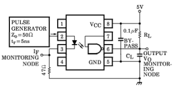
In place of pulse generator there is the MIDI cable, connected to pins 2 and 3 with a 330 ohm resistor in series. I’ve omitted the capacitors on the input side and connected pin 7 to VCC to enable the circuit permanently. Here are the actual connections needed:
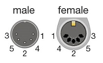
- Pin 5 of the MIDI DIN connector (second from the left when you look at the pins) goes to pin 2 of the 6N137 (brown jumper cable in the picture)
- Pin 4 of the MIDI DIN connector (second from the right when you look at the pins) goes via 330 ohm resistor to pin 3 of the 6N137 (so the 6N137 pins and the resistor are connected in series)
- You should also have a reverse connection protection diode between pins 2 and 3 of the 6N137 but I like living dangerously and rely on the diode inside the 6N137
- Pin 8 and 7 are connected to ATmega32u4 VCC (red jumper in the picture)
- Pin 6 is connected to RX
- Pin 5 is connected to GND
- 2 kohm pullup resistor between pin 8 and 6 (VCC and signal out)
- If you want to protect the LED inside the 6N137, put a 1N4148 diode between pins 2 and 3 (the opposite way the internal LED is connected, see 6N137 diagram)
Just a reminder: Pin 1 on DIP packaged chips is marked with a depressed circle, and the numbering then runs counter-clockwise!
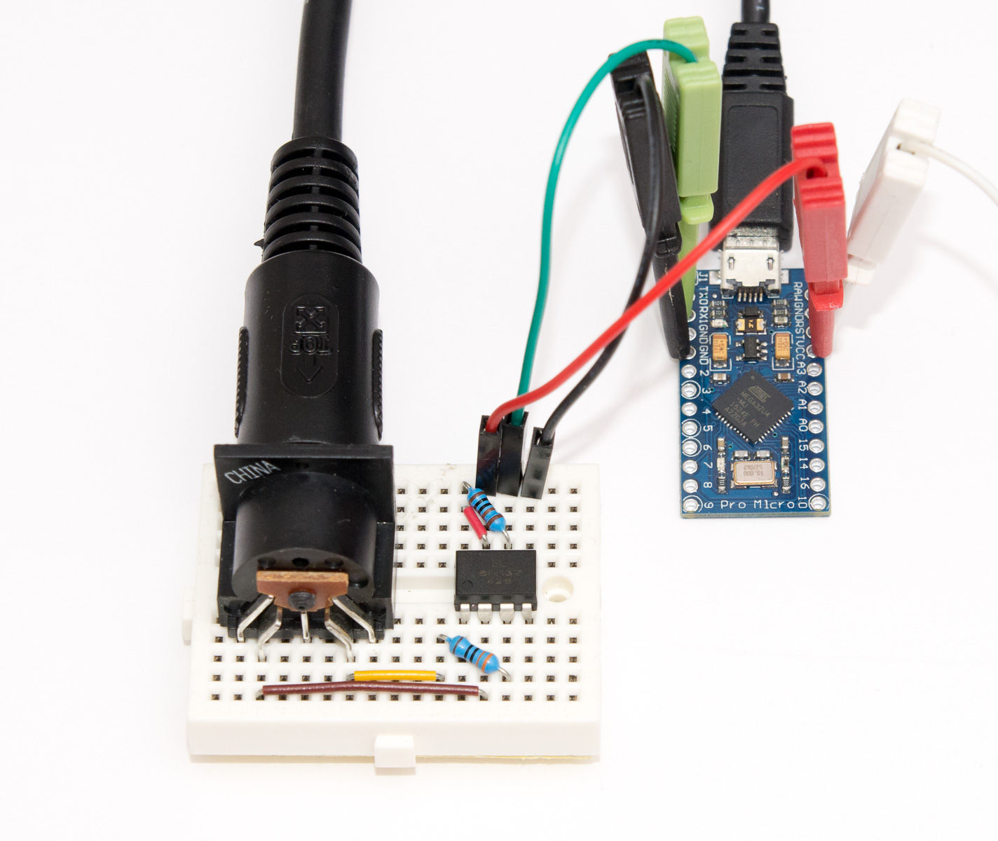
That’s it! Take a second look at my wiring diagram (click the image for a crisper full size version) if you are in doubt. The most obvious way to screw this up is to reverse DIN connector pins, but the 6N137 quite likely survives this reverse connection, so just swap them first if your circuit doesn’t seem to work!
The code
Procedure for flashing the actual MIDI adapter code is identical to earlier ATmega32u4_miditest, just repeat that but use files from this zip instead to replace the standard MIDI demo: ATmega32u4_midiadapter.zip.
Below is the beef of the code — basically we turn on the hardware USART, and translate the received MIDI events into USB MIDI commands. A couple of additional notes:
- If
DEBUGis defined, all received data is sent back to TX pin to help debugging. - The baud rate, 32150 is not a mistake — even though the MIDI spec says 31.25 kHz, I found out the AVR USART implementation misses consecutive bytes with this exact speed due to START edge being not detected. A slightly higher baud rate fixes this nicely.
- My
receiveUART()function currently only handles note on, note off and controller messages (i.e. pedal), so this is mainly for playing a piano, not for a hardcore MIDI controller that might send something else.
#define DEBUG
void USARTInit(unsigned int ubrr_value) {
cli();
//Set Baud rate
UBRR1H = (unsigned char)(ubrr_value >> 8);
UBRR1L = (unsigned char)(ubrr_value & 255);
//UCSR1A &= ~(1 << U2X0); // Disable double speed
// Frame Format: asynchronous 8-N-1
//Enable the receiver
#ifdef DEBUG
UCSR1B = _BV(RXEN1) | _BV(TXEN1); // echo RX on TX
#else
UCSR1B = _BV(RXEN1);
#endif
UCSR1C = (0 << USBS1) | (3 << UCSZ10);
sei();
}
/** Main program entry point. This routine contains the overall program flow, including initial * setup of all components and the main program loop. */ int main() { uint16_t debounce = 0; uint8_t keydown = 0;
/* Disable watchdog if enabled by bootloader/fuses */ MCUSR &= ~(1 << WDRF); wdt_disable();
/* Disable clock division */ clock_prescale_set(clock_div_1);
/* Hardware Initialization */ USARTInit(F_CPU/16/32150); LEDs_Init(); LEDs_TurnOnLEDs(LEDS_LED1); // keep LED1 on until initialized USB_Init();
GlobalInterruptEnable();
while(1) { receiveUART();
MIDI_EventPacket_t ReceivedMIDIEvent; // Discard received events, see actual MIDI example for code to do something while(MIDI_Device_ReceiveEventPacket(&Keyboard_MIDI_Interface, &ReceivedMIDIEvent)) { }
MIDI_Device_USBTask(&Keyboard_MIDI_Interface); USB_USBTask(); } }
void receiveUART() { static enum { NOTEON, NOTEOFF, CONTROL, OTHER } state = OTHER; static uint8_t msg, data[2], dp=0;
if(!(UCSR1A & (1<<RXC1))) return; // no data waiting
// There are several limitations to the code below: // 1. System real-time messages ignored // 2. Only note on, off and control change handled // 3. Channel number ignored msg = UDR1; #ifdef DEBUG UDR1 = msg; // echo on TX for debugging LEDs_ToggleLEDs(LEDS_LED2); #endif
if(msg & 0x80) { // MIDI status byte switch(msg >> 4) { // Remove channel case 0xB: state = CONTROL; dp = 0; break; case 0x8: state = NOTEOFF; dp = 0; break; case 0x9: state = NOTEON; dp = 0; break; default: // Just forget everything else for now, including // 0xF8 (time) and 0xFE (active sensing) //state = OTHER; break; } } else { // MIDI data byte data[dp++] = msg;
if(dp >= 2) { switch(state) { case NOTEON: sendMIDI(MIDI_COMMAND_NOTE_ON, 0, data[0], data[1]); break; case NOTEOFF: sendMIDI(MIDI_COMMAND_NOTE_OFF, 0, data[0], data[1]); break; case CONTROL: sendMIDI(MIDI_COMMAND_CONTROL_CHANGE, 0, data[0], data[1]); break; default: // ignore break; } dp = 0; // ready for running status } } }
That’s it! Once you have flashed this firmware to your device, you should be able to connect the adapter between a piano with MIDI OUT and a computer with USB port (welcome to the new millennium) and fire up Pianoteq or whatever DAW you like, and play away. Not bad for a day’s work!
Final remarks
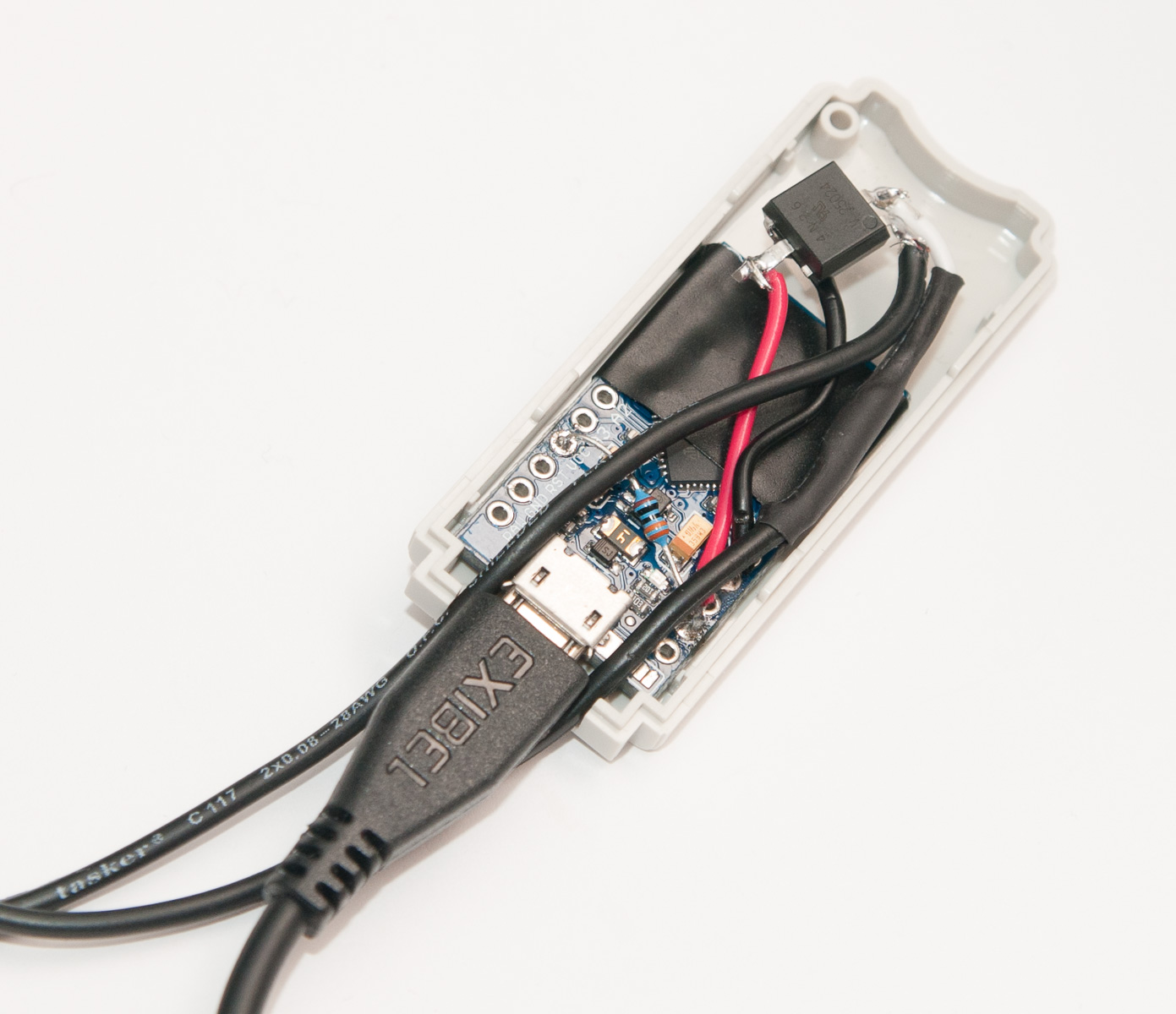
Once you have the circuit working, you might want to make some kind of enclosure for your device. I used a different DIP6 packaged optocoupler (4N26) to fit everything inside a USB dongle sized container. You can see the space-saving method of soldering the pullup resistor straight between VCC and RX pin I devised to make everything fit, and the ugly but efficient tip of cutting of non-connected legs of the optocoupler off.
If I’d do this again, I would probably buy or 3D print a slightly larger box enclosure to fit the components with less hassle, and also hopefully secure the wires coming from MIDI connector better to the case. But all this is left for exercise to the reader. Thanks for reading!