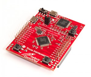
TI Stellaris Launchpad Test Run
Mon, Oct 15, 2012 in post Electronics arm cortex cortex m4 drivelib launchpad stellaris launchpad stellarisware texas instruments ti
My local electronics store Partco overdid themselves again. Believe it or not, while most of the people in US are still waiting their Stellaris Launchpads, this small Finnish electronics outlet had several in stock. Thanks to two generous donators of $11 and $1.5 respectively, I also had the financial leverage to acquire one. :)
The board came in a decent black cardboard box with a small quickstart booklet – see Hack-a-Day hands on coverage for details on the package. Even the board itself contains the URL where you can get the software package. I proceeded to download the 1.3 GB Code Composer Studio + StellarisWare package. It took 30 minutes to download, thanks to less-than-impressive transfer speeds from TI, and another 1 hour to install.
The guys at TI were generous enough to include working quickstart / driver installation guide with the package, and for once, I was actually able to walk through it without any “oh this doesn’t work anymore” -moments. Even the three drivers required were found under Software/ICDI in the setup package. Kudos! As a result of installing CCS and StellarisWare, I now had 3.75 GB and 63 872 files of additional hacking capability on my hard drive. Gone are the days where you could fit an IDE into four floppies like my Borland Turbo C++ 3.0!
Taking it for a test drive
I first followed TI’s quickstart tutorial to the end to get some blinky LED action, and even tried out the UART example – even that worked out of the box with Putty set to COM25 and 115 200 baud rate. Next I made my own project by shamelessly following the recent HaD Getting Started guide.
Sure enough, the LEDs were now blinking just like I wanted them to – and blinding me in the process: whoever thought that you need SMD LEDs that are bright enough to leave light trails on my retina must’ve been utterly mad. I recommend either wearing sunglasses (might not be enough – seriously) or placing something near-opaque (like a piece of white paper) between yourself and the Launchpad when working with the LEDs for any longer periods.
However, I couldn’t yet find much information about input side, so after some searching, I located the documentaion for StellarisWare peripheral drivel library, SW-DRL-UG-9453.pdf and started reading. Armed with that and the short “Stellaris LM4F120 LaunchPad Evaluation Board User Manual” that was found from Documentation/Board/EK-LM4F120-UM.pdf I quickly wrapped up something that was supposed to turn red and green LEDs ON when pressing user switches SW1 and SW2, respectively:
#include "inc/hw_gpio.h"
#include "inc/hw_memmap.h"
#include "inc/hw_sysctl.h"
#include "inc/hw_types.h"
#include "driverlib/gpio.h"
#include "driverlib/sysctl.h"

#define LED_RED GPIO_PIN_1
#define LED_BLUE GPIO_PIN_2
#define LED_GREEN GPIO_PIN_3

#define BUTTON_1 GPIO_PIN_0
#define BUTTON_2 GPIO_PIN_4

void main(void) {
	int light;

	// configure system clock to run at 50 MHz
	// use external crystal (16 MHz) and PLL
	SysCtlClockSet(SYSCTL_SYSDIV_4|SYSCTL_USE_PLL|SYSCTL_XTAL_16MHZ|
        SYSCTL_OSC_MAIN);

	// Enable PORT F GPIO
	SysCtlPeripheralEnable(SYSCTL_PERIPH_GPIOF);

	// set LED pins as outputs
	GPIOPinTypeGPIOOutput(GPIO_PORTF_BASE, LED_RED|LED_BLUE|LED_GREEN);

        // SEE COMMENTS IN THE POST

	// set user switches as inputs
	GPIOPinTypeGPIOInput(GPIO_PORTF_BASE, BUTTON_1|BUTTON_2);

	// turn weak pull-ups on
	GPIOPadConfigSet(GPIO_PORTF_BASE, BUTTON_1|BUTTON_2, GPIO_STRENGTH_2MA,
        GPIO_PIN_TYPE_STD_WPU);

	// loop forever
	for (;;) {
		light = 0;

		if(!GPIOPinRead(GPIO_PORTF_BASE, BUTTON_1))
			light |= LED_RED;

		if(!GPIOPinRead(GPIO_PORTF_BASE, BUTTON_2))
			light |= LED_BLUE;

		GPIOPinWrite(GPIO_PORTF_BASE, LED_RED|LED_BLUE|LED_GREEN, light);

		SysCtlDelay(500000);
	}
}
Notice that I also needed to turn pull-ups on, otherwise the buttons didn’t work properly. After compiling this, I found out that it almost worked – SW1 was working fine, but SW2 was not responding, instead staying low all the time.
Turns out that Port F pin 0 it’s connected to has additional uses, and needs “unlocking” before it can be used as a normal switch. Because the Launchpad is quite new, this information is not very readily available anywhere. Thankfully some of the Launchpad examples use both buttons, and I was able to locate the required code to unlock PF0:
// Unlock PF0 so we can change it to a GPIO input
// Once we have enabled (unlocked) the commit register then re-lock it
// to prevent further changes.  PF0 is muxed with NMI thus a special case.
HWREG(GPIO_PORTF_BASE + GPIO_O_LOCK) = GPIO_LOCK_KEY_DD;
HWREG(GPIO_PORTF_BASE + GPIO_O_CR) |= 0x01;
HWREG(GPIO_PORTF_BASE + GPIO_O_LOCK) = 0;
Inserting this piece of code before setting PF0 and PF4 as input (the line that says “SEE COMMENTS IN THE POST” above) I got everything working. Cool! Next I’m going to try out the UART and USB functionality on more detail, to see if I could get the Launchpad to do something more exciting than just blink a LED!


2 comments
ducksauz:
I’ve run into those kind of LEDs before. A while back, a friend and I were working on a project using the Redwire Redbee 802.15.4 module. When you reset the module, it would default to bright white on the SMD RGB led on the board. We took to referring to them as the “eye raper” LED.
kadorek:
hi ,
i am trying run this code but always i had a error in ccs 5 #10010, #10234-D and one more without id . i suppose it happens because of linking problem . can u help me about this problem.