Breakout Bonanza and DS1307 Realtime Clock
Sun, Aug 26, 2012 in post Electronics adafruit breadboard breakout bus pirate ds1307 i2c realtime clock rtc sparkfun
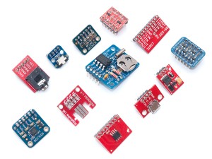
As if I didn’t have enough things on my “to try when I have the time” list already, I recently did a little shopping in both Adafruit and SparkFun. Both had several nifty breakout boards available that promised to speed up and streamline my breadboard projects a lot. In addition to some SMD breakouts that are still in their sealed bags, here’s what I got:
- A four-channel bi-directional level shifter, promised to work also with I2C and SPI
- A similar 2+2 level converter from SparkFun
- A MAX3232 breakout – it cost the same as the DIP version here in Finland, and came with SMD capacitors. Nice!
- A 3-axis accelerometer with I2C interface
- MCP4725 12-bit DAC with I2C interface
- A NCP1402 5V step-up converter
- A DS1077 programmable oscillator (frequency generator)
- Useful breadboard adapters for 3.5mm audio, micro-USB, touch screen and Wii Nunchuck connectors (saves me from dangling wires)
- Finally, a DS1307 realtime clock breakout
I had a lot of fun soldering the breadboard headers to these little guys. Many are for future projects, like the frequency generator which I’m planning to use for some RFID experiments, and some are just to avoid stripping apart stuff like the connector breakouts. As today’s main topic, I’m covering the DS1307 realtime clock (RTC) breakout in more detail. If you are interested in some of the other items, drop me a comment and I’ll get back to it!
DS1307 Realtime Clock
A realtime clock is simply something that keeps record of the time. Usually, these types of clocks are paired with a small coin cell battery that enables them to keep on counting even if the rest of the circuit is powered of. Such is the case with this breakout, too. Adafruit has an excellent tutorial covering the assembly of this device, all you need is some solder and an iron.
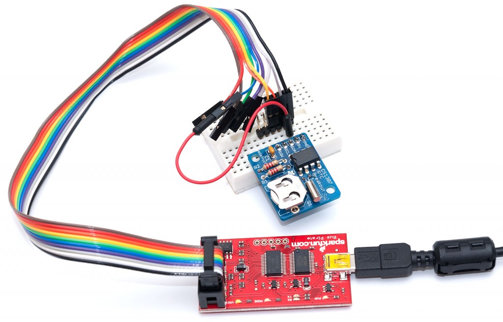
After getting it together, it took me a while to get it working. I used Bus Pirate to communicate with the chip, with the following connections:
- GND wire (black) to GND pin
- 5V wire (grey) to 5V pin
- Jumper cable from that same 5V rail to VPU wire (blue)
- MOSI wire (orange) to SDA pin
- CLK wire (yellow) to SCL pin
After that, I just set a slow I2C mode (m 4 and 5 kHz), enabled power supplier (W) and pullups (P), checked that the Vpu actually is 5V (v) and scanned for devices with the (1) macro. As you can see, the device is found with I2C address of 0x68, which translates to 0xD0 read address and 0xD1 write address – the I2C address is shifted left by 1 bit and the LSB tells whether the operation is read (1) or write (0).
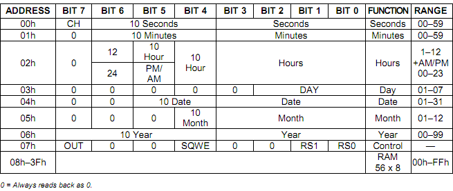
From programming and reading viewpoint, the device is just 64 bytes of memory that can be read and written. The first 8 bytes contain the clock counter and have a special meaning. The full Maxim DS1307 datasheet explains it in detail, but their table summarizes it rather well, too:
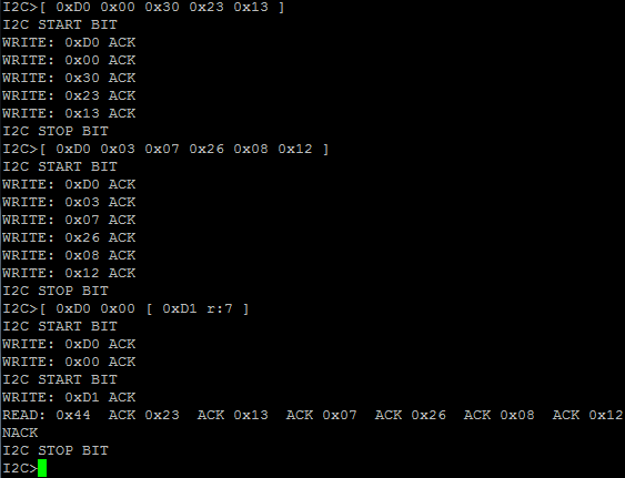
If we’d like to set the time, we send I2C start, then the device address, next the memory offset we want to write, followed by data and I2C end. The memory offset is automatically incremented, so we can easily program consecutive bytes of the memory. For example, to set time to 13:23:30 (24 hour format), we can just use (in Bus Pirate notation, [ is start and ] is end):
[ 0xD0 0x00 0x30 0x23 0x13 ]
Note how we first send the seconds, then minutes, and finally hours. Most of the fields take BCD (binary coded decimal) values, i.e. tens are in the upper 4 bits and digits in the lower 4, so instead of “30” we actually write the hex “0x30” (48 in decimal). Date is set in a similar manner. Address 0x03 contains the weekday (I’ll use 7 for Sunday, sorry folks), the rest contain date, month and year, so setting date to Sunday, 26th August 2012 becomes:
[ 0xD0 0x03 0x07 0x26 0x08 0x12 ]
Reading is done by first “writing zero bytes” to set the memory offset, then just sending a new start token and acknowledging any received bytes until we want to stop. Let’s read all those 7 bytes we just wrote:
[ 0xD0 0x00 [ 0xD1 r:7 ]
And what do you know, it also works in practice! See how the seconds counter has already advanced from 0x30 to 0x44 during those 14 seconds it took me to copy-paste this stuff:
That’s it for now. I think I’m going to learn a bit of I2C interfacing with Arduino and AVR next, and write a short tutorial on that subject next time!


