PicoScope 2204 USB Oscilloscope Review
Sat, Feb 18, 2012 in post Electronics Reviews bitscope oscilloscope picoscope picoscope 2204 picotech review scope usb oscilloscope
One of the nicest things when starting a new hobby is that there’s just so many things you don’t yet have, and can thus look forward to researching and then maybe buying if the price is right. In electronics, you can pretty much get started with a $10 soldering iron, $25 multimeter, maybe a $30 programmer if you want to use microcontrollers, and then just buy cheap components to tinker with. But sooner or later, you start thinking about how nice it would be if you had an oscilloscope.
For me it took about nine months. I saw an article on using AVR as an RFID tag and noticed I could build a simple RFID reader with a few components. However, to really learn something, it would be nice to actually see the 125 kHz RFID carrier wave instead of fumbling blindly with the schematics. Additionally, I could use the scope to verify DIY D/A circuits, maybe debug serial protocols and much more. So I started researching.
Getting a used analog or digital scope from eBay was of course one option. However, old scopes are big, clunky and I don’t really have much table space. And if the scope fell out of use, it would be wasting space in a closet. New Chinese-made digital scopes from Owon and Rigol looked good and were relatively small and light. However, they had 640×480 or 800×600 displays and I had 2560×1600 30″ monitor sitting on my workspace, and being more of a software person, I eventually decided against them and chose to get a PC scope instead.
Options in USB scopes
Going through the options for digital scopes, there seemed to be a few price brackets:
- At around $50 you could get a cheap scope of unknown origin
- A few brands such as Parallax and Stingray had offers around $150-$200 – less toylike, but still not very serious on features and the range of scopes offered by the manufacturers were somewhat limited
- PicoTech and BitScope had a range of offerings from $250 onwards
- Tektronix and Agilent had USB options or dedicated PC scopes, but in the $1000+ price range
The middle ground seemed a safe choice – I would not be spending too much in case the scope would not get much use (I could always get a more expensive one later) and on the other hand I wouldn’t immediately get the “I really need to get a better one soon” feeling. After reading some reviews, digging through forums and looking what the different electronics retailers were carrying (mostly PicoScope), I chose to go with PicoTech.
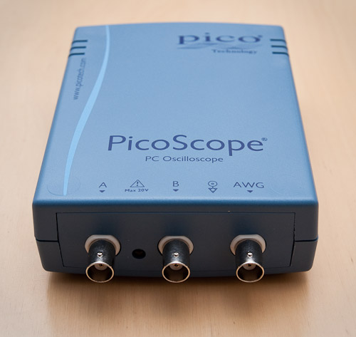
PicoScope 2204
PicoTech has a wide range of scopes from $150 handheld 1-channel models to $23 000 sampling oscilloscopes. I wanted to have least two channels so the 2204 model at $262 was the cheapest option. Higher models in 2000 series had better bandwith, but all shared rather limited buffer size (8-48 kilosamples, i.e. around 1 microsecond of data or less at maximum sampling rate). However, the 3000 series which had larger buffers started from $660, so I decided to start with a basic model that would be easy to sell if I’d ever outgrow it. Following the same logic, I decided 10 MHz would be enough for now, as price quickly rose for 25/50/100/200 MHz models:
http://www.picotech.com/picoscope2000.html
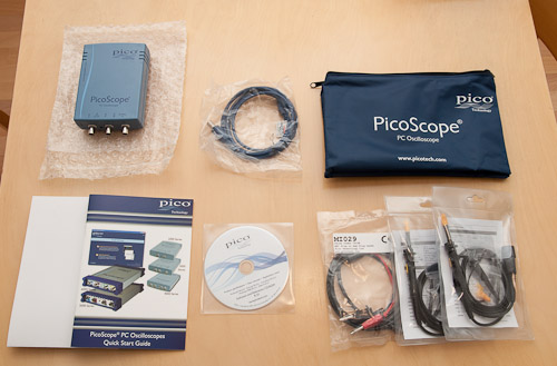
I ordered the scope, a set of 60 MHz probes and a BNC to banana jacks cable for the arbitary waveform generator. The entire package was about 300 € with taxes (inside EU) and express shipping. It arrived in few days, packed nicely and all pieces in perfect shape:
Features at glance
You can get the full rap from the PicoScope2200 datasheet, but here are the basic features of 2204:
- Two channels, BNC input, 1 Mohm, 20pF
- 10 MHz bandwith with 100 MS/s sampling rate
- 50 MS/s sampling with two channels, 2 GS/s for repetitive signals
- Input ranges from +-50 mV to +-20 V
- 8-bit resolution with +-3 % DC accuracy (of full scale)
- 8 k sample buffer
- Arbitary waveform generator, includes sine, square, triangle, …
- AWG frequency from DC up to 100 kHz signals
Setup and software
For a PC-connected oscilloscope, the software is where most of the action happens, and the hardware is basically just a low-noise, high impedance A/D converter with extremely high sampling rate. PicoScope does triggering based on digitized data, so even that part of the functionality is covered in software.
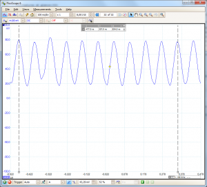
Setup was very straightforward, just install the PicoScope software and plug the device in. Unlike many other devices, PicoScope did not have any issues with 64-bit Windows 7. You can download the software without the scope and it will work in demo mode, I really recommend this if you want to get a feel of the software and how it works. My oscilloscope use before PicoScope totals at about 5 minutes and that was 15 years ago, and I managed to navigate around the software without reading the help files too much, so it’s pretty intuitive:
The picture above shows a measurement of 12 MHz crystal oscillator use in my USB tutorial. Note that this is beyond the specified 10 MHz bandwith, but the wave still renders beautifully. When I put markers to 10 wavelengths it measures 834 ns between the markers, which translates to 11.99 MHz. Not bad! Note that a 1 pixel mistake when placing the markers is larger than the 0,08 % error in this measurement. :)
Advanced functionality
Already the basic 2-channel oscilloscope features easily available in PicoScope software made my purchase worth its price. In a few weeks, I’ve used it to understand different PWM generation modes in ATtiny2313, verify that a hand-built D/A converter using R-2R network really works, tested the current/drop voltage curve of a diode and checked that my microcontroller outputted proper square wave signals for directly driving an LCD.
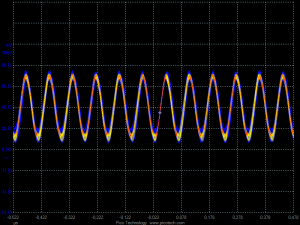
However, software functionality offered by PicoScope does not end there. In addition to the plain oscilloscope view, there’s a mode for emulating traditional oscilloscopes (older signals fade off so you get the idea of signal variance):
Also, there’s a spectrum analyzer (which is unfortunately limited by software to the specified bandwith of device, in my case to 10 MHz) view. And you can create custom “maths channels” that are not limited to standard A+B, A*B and A-B sort but you have a wide array of operators at your disposal. For example, if you are measuring a voltage over a 68 ohm resistor in channels A and B, you can display the current through the resistor by using a custom “(A-B)/68” channel (remember, U=RI so I=Uab/R).
Furthermore, what the existing software does not offer, you can implement yourself. PicoTech offers a full SDK which you can use to develop different kinds of programs that interface with your PicoScope using a wide variety of languages. For example, I’m thinking that once I get my RFID antenna and 150 kHz carrier wave generator done, I could stream data from PicoScope at 2Ms/s to custom software that could analyze the carrier wave modulation on PC so I understand the signal better before I try to decode the modulation in hardware.
Serial decoding
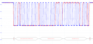
Finally, the newer PicoScope software versions support serial decoding. I made my first foray to I2C communication just a week ago, and debugging the unresponsive chip became really easy when PicoScope showed that my signal was correct, but the I2C chip did not send ACK response to my microcontroller – I had the device address wrong (data sheet gave 2 alternatives for different models of the chip)!
Minor quibbles
While the PicoScope has been a very positive experience overall, there are of course some limitations to this entry-level model (otherwise they wouldn’t sell any other models). 10 MHz bandwith means that most radio frequencies you encounter won’t be directly visible. Unlike normal view, the spectrum analyzer is also limited to 10 MHz as well as frequency measurements so analyzing signals above this is not possible even if the hardware’s 100 MS/s sampling rate theoretically would allow this (with some uncertainty).
Also, unlike stand-alone oscilloscopes, USB scopes usually have a limited measurement range, and same applies to PicoScope 2204 – maximum range is +-20 volts (1:10 probes do alleviate this a lot, though). Also, only ground you can have is the same one you get from USB port (the same as your computer, and which may or may not match what you get from other DC power supplies) so if there’s a DC voltage between that and the ground of device you want to measure, you need expensive active probes.
For basic electronics projects the voltage capabilities are quite enough, but any “power electronics” is not the natural domain of this model (PicoTech has a more expensive model, PicoScope 3425 which has differential inputs) and AC mains measurements are explicitly prohibited in the manual.
And of course, unlike BitScope’s mixed signal oscilloscope that features 8 digital inputs, you are limited to 2-wire serial protocols. There’s a PicoScope 2205 MSO model with 16 digital inputs if you want that type of hybrid device.
Conclusions
As I have effectively zero experience on other oscilloscopes, I cannot say how it compares to other products in the market or if “a real oscilloscope” would offer some advantages over this one. For me, the possibility to make an instant screen capture of a display or interface with the device from PC outweighs the drawbacks of such a “virtual device”.
Pros
- Very small footprint on desktop
- Light but sturdy build
- Hardware capability easily matches the price
- Easy to use software with powerful features such as serial decoding
- 10 MHz, 2 channels, 100 MS/s sampling rate more than enough for hobbyist use
- SDK makes it possible to use it as very capable data capture device
- Powerful signal generator in the same package
- Clear upgrade path if I want beefier models
- Fast delivery, good customer service and 5 year warranty
Cons
- Limited voltage range (-20..20V, not recommended for mains AC)
- 10 MHz bandwith limit also imposed in software size
- Not quite shirt pocket-sized (coat pocket sized, yes)
- Small buffer (good for viewing but not for signal recording)
- Continuous data capture rate limited to 2-3 MS/s (USB 2.0)
Overall, I have been very satisfied with my PicoScope and as a electronics hobbyist can very much recommend it to anyone with similar needs. In time I will learn to use the scope even better and probably find a useful function or two in the software, too. Or maybe I found something to improve. In that case, I’ll probably add a new post on the subject.
11 comments
Birger:
Great article. Thanks for the insight before I am buying my own PCO.
Brandon:
Fine article. Looks like an excellent choice. I will likely spring for one of these soon!
HolaHola:
Hey, thx for the insight, very usefull, even though you havent used “nomal” scopes :)
ivo:
>maximum range is +-20 volts (1:10 probes do alleviate this a lot, though).
and 1:100 should alleviate it further.
as for the warning in user manual that states: “To prevent injury or death, the oscilloscope must not be directly connected to
the mains (line power). To measure mains voltages, use a differential
isolating probe specifically rated for mains use, such as the TA041 listed on
the Pico Technology website.”
perhaps they like to sell those ultra-expensive diff. probes of theirs?
keyword in that quote is “directly”, and then nobody should probe mains voltage directly with any scope as that will usually be waay out of range of vertical amp.
another important warning there:
“WARNING
Never connect the ground input (chassis) to any electrical power source. To
prevent personal injury or death, use a voltmeter to check that there is no
significant AC or DC voltage between the oscilloscope ground and the point to
which you intend to connect it.”
but that too goes for other scopes too.
A. Sørensen:
See new version of PicoScope 2000 at [MicroTec.dk website]
Joonas Pihlajamaa:
Mr. Sörensen, sorry to redact your URL but I felt direct link to individual store would be slightly too direct endorsment. For those interested, all PicoTech distributors are available here:
http://www.picotech.com/distribl.html
ivo:
regarding these cons:
>Small buffer (good for viewing but not for signal recording)
>Continuous data capture rate limited to 2-3 MS/s (USB 2.0)
what is, then, the bandwidth in the streaming mode, full 100ms/s / 2 which means 50 times lower, ie 200khz?
what amount of time can it record with it’s own buffer?
you essentially say this is not really scope to record transient events of any sort?
Joonas Pihlajamaa:
Because maximum streaming is around few million samples per second, bandwith is at most half that, i.e. 1-1.5 MHz. But if you want details in the waveform, your 200 kHz is a fair estimate. Internal buffer is 8 kilosamples, so at 100 MS/s it will fill in microseconds. So the 2204 entry level scope is definitely not for transient events, unless the frequency is very low (under 1 MHz).
ivo:
yeah, but it’s still somewhat of a surprise that in 21st century you still don’t have a decent small box that you hook on to tv and you have a decent storage scope with big screen..probably because it’s a niche product, never to be mass produced ergo cheaply….regarding 2204, if it can’t capture then used analog scope seems a better idea, for the money….ie same money gets you more analog bandwidth…
“Memory Depth” chapter here
http://www.picotech.com/applications/oscilloscope_tutorial.html
was an eye opener, as that 4,43 burst looks really crappy when buffer is small…
ivo:
do you have an option to move trigger left/right arbitrarily (even off the screen) like on this rigol video
https://www.youtube.com/watch?v=gxXenzhmz_E
(orange marker in the top denotes trigger position in time )
i presume trigger voltage level you probably have (?)
thanks
Joonas Pihlajamaa:
The trigger level and position can be set freely. I don’t remember if there’s arbitary delay, but most likely there is. You can check with the Picoscope software by yourself, it works in demo mode even without a scope.